
Polishing and buffing operators, toolroom personnel, supervisors, production engineers, maintenance personnel, QA/QC teams and technical buyers
Base preparation; compounds and polishing media; contamination; scratches; drag lines; haze; low or patchy gloss; swirl; smearing; relief; edge rounding; pitting; pull-out; orange peel; heat effects; correction and verification.
- Inspect machine, guards, mounting and polishing media before use.
- Secure the component and maintain a stable position outside the ejection path.
- Tie back hair and control loose clothing, jewellery, gloves and rags around rotating machinery according to the safe work method.
- Use suitable eye, face, hearing, hand, body and respiratory protection.
- Capture dust and control combustible accumulations for the actual material.
- Keep compounds, cleaners and solvents away from incompatible heat and ignition sources.
- Isolate energy before cleaning, adjustment or media change.
- Treat cracking, pitting, burn and geometry loss as technical conditions, not merely visual defects.
Polishing refines an already controlled surface. It cannot reliably correct deep damage, waviness, poor geometry or thermal defects, and excessive polishing can make the surface worse.
A bright surface is not automatically a conforming surface. The required result may include gloss, texture, direction, flatness, edge retention, cleanliness, coating readiness or mould-release function. Confirm each requirement before polishing or rework.
When an exact product value is required, Refer to the product label, Technical Data Sheet, or MKTECH representative.
Chapter objectives
After this chapter, the reader should be able to:
- confirm the required polishing endpoint and inspection method;
- establish a uniform, damage-free base before polishing;
- prevent cross-contamination between compounds and stages;
- diagnose scratches, haze, swirl, smearing, relief, pitting and orange peel;
- recognise when polishing time or pressure is worsening the surface;
- correct the earliest responsible stage without excessive stock loss; and
- verify appearance, geometry, cleanliness and downstream function.
Define the polishing endpoint
Use the drawing, controlled sample, customer specification or workmanship standard. Establish:
- whether the finish is visual, measured or both;
- permitted scratch direction and viewing orientation;
- agreed lighting, distance and comparison method;
- surface-texture parameter and measurement direction where specified;
- flatness, contour, edge and dimensional limits;
- cleanliness and residue requirements;
- coating, plating, sealing, hygiene or moulding function; and
- maximum permissible material removal.
ISO surface-texture documents distinguish indication, terminology and specification conditions. [S343–S345] Do not invent a universal “mirror” grade or use gloss alone as proof that all requirements pass.
Stop conditions
Stop polishing when there is:
- a crack, seam, lap, delamination or unexpected pit requiring assessment;
- rapid surface deterioration, orange peel or widespread pull-out;
- heat tint, burn, distortion, smoke or ignition;
- abnormal vibration, noise, tool damage or loose mounting;
- a torn, contaminated or unstable mop, pad or cloth;
- unexpected compound spray, dust escape or failed extraction;
- loss of component control or unsafe line of fire; or
- uncertainty about material, coating, product or machine compatibility.
Isolate equipment before inspection, adjustment, cleaning or media change.
Establish a uniform base first
Polishing should begin only after the preceding grinding or finishing stage has produced a uniform surface and removed earlier damage. Check the surface at transitions, edges, recesses, weld zones and previous repair boundaries.
If a deep scratch remains, additional fine polishing may brighten the surrounding surface while leaving the scratch intact. This reduces stock elsewhere and makes correction harder. Materialographic guidance requires complete removal of preceding damage before advancing. [S123; S148–S149]
Classify polishing defects
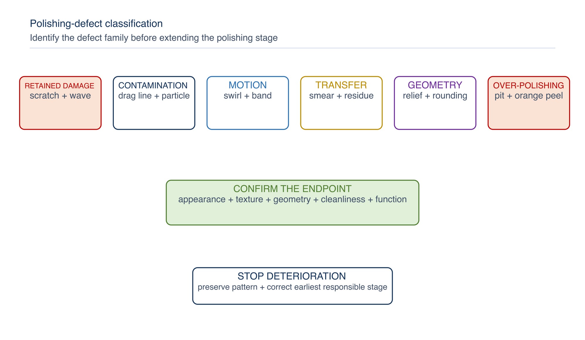
| Defect family | Common appearance | First investigation |
|---|---|---|
| Retained damage | deep line, grinding mark, waviness | previous-stage completeness and stock condition |
| Contamination | random coarse scratch, drag line, embedded compound | media, work, handling and workplace; particle cleanliness |
| Motion variation | swirl, arc, band, patchy reflection | stroke, contact, workholding, runout and overlap |
| Material transfer | smear, streak, loaded media, residue | cutting action, lubricant or compound behaviour, heat |
| Geometry change | rounded edge, relief, hollow or low spot | media compliance, dwell, pressure, support and access |
| Over-polishing | orange peel, pull-out, pitting, worsening surface response | polishing duration, contact severity and material |
Control cleanliness between stages
One coarse particle can create a defect across a nearly finished surface. Keep separate and clearly identified:
- compounds, suspensions or bars;
- mops, pads, cloths, felts and brushes;
- application tools and containers;
- work supports, clamps and handling materials;
- cleaning cloths and inspection gloves; and
- storage for clean and used media.
Clean the component, fixture, machine and immediate work area before moving to a finer stage. Do not place a clean tool on a contaminated bench. Keep lids and protective covers closed when products are not in use.
Use a polishing-stage cleanliness gate
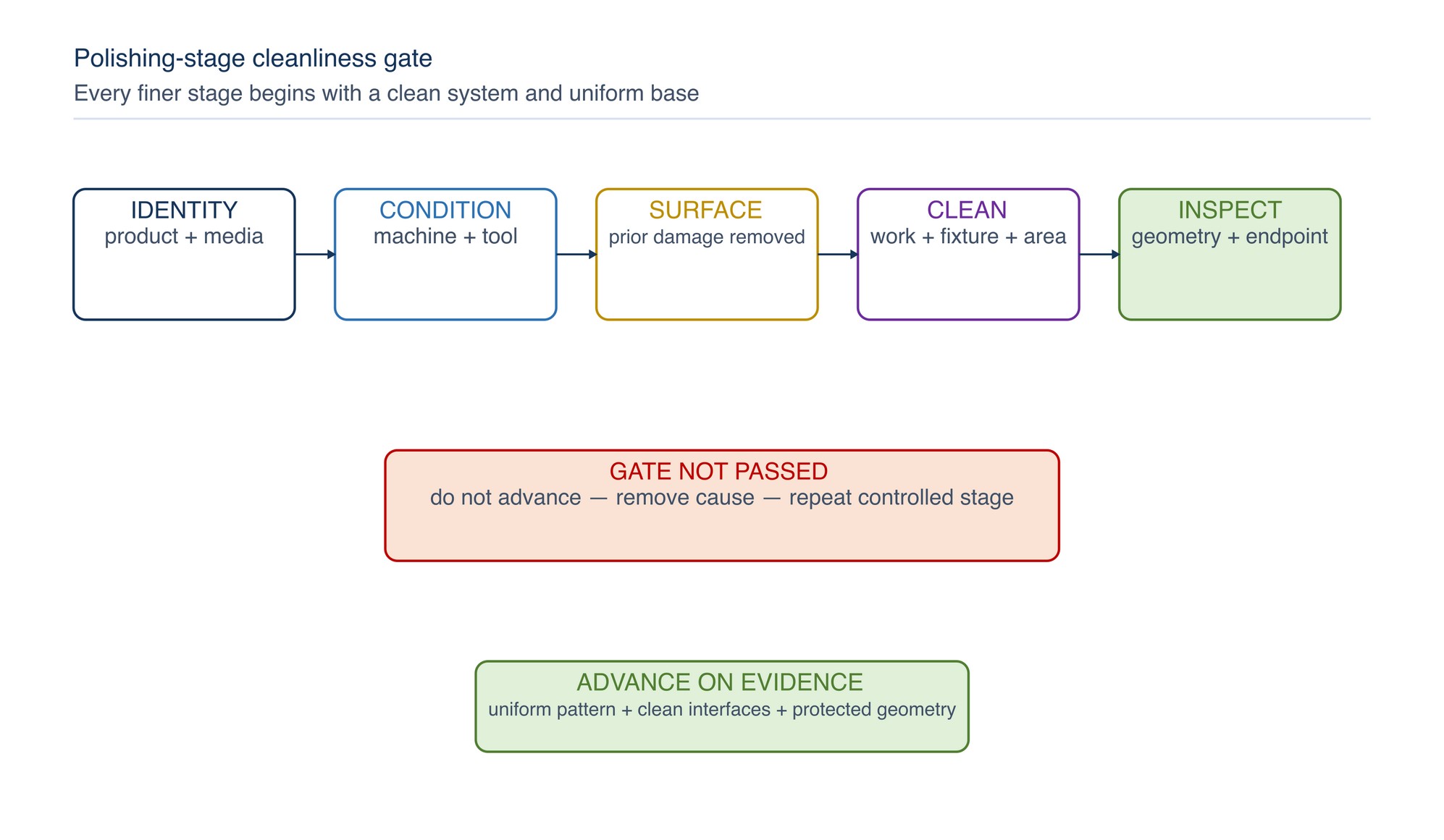
At every stage, confirm:
- correct product and media identity;
- clean, serviceable machine and contact media;
- uniform base condition;
- previous damage removed;
- geometry remains within requirement;
- controlled cleaning complete; and
- inspection passed under comparable conditions.
Deep scratches that remain after polishing
Determine whether the line follows the current polishing motion or crosses it. A crossed line usually predates the current stage. A fresh line matching the motion may come from debris, damaged media, compound agglomeration or a hard particle released from the work.
Do not chase one deep scratch with prolonged local polishing. Preserve the pattern, clean the system, confirm available stock and return to the earliest stage capable of removing the defect uniformly.
Random scratches and drag lines
Random or sudden drag lines commonly indicate contamination, a loose hard particle, dried compound, damaged cloth, a sharp component feature contacting the media or debris trapped during wiping.
Check when the line begins and whether it repeats with tool rotation. Quarantine contaminated media, clean all interfaces and inspect the component for a particle source. Buehler and Struers guidance link late-stage coarse scratches with cross-contamination and incomplete cleaning. [S123; S148–S149]
Haze, cloudiness and low gloss
Possible causes include:
- incomplete removal of the preceding pattern;
- uneven compound distribution;
- contaminated or overloaded media;
- unsuitable media condition or compliance;
- residue left by cleaning;
- variable contact pressure or dwell;
- local geometry changing reflected light; and
- surface relief or early over-polishing.
Clean by the approved method before concluding that texture is defective. Inspect under stable lighting. If the haze is within the surface, restore a uniform earlier stage rather than repeatedly polishing the cloudy patch.
Patchy gloss, bands and swirl
Patchy reflection can follow inconsistent overlap, hand pressure, tool angle, mop loading, workpiece temperature or local rework. Swirl or arc marks may reflect rotary motion, abrasive-edge contact, runout or a mismatch between the tool action and specified direction.
Correct the motion and mechanical source first. Blend to a natural or specified boundary; isolated spot work can create a visible halo or low area.
Compound streaks, build-up and residue
Too little active cutting, excessive product application, dirty media or excessive heat can produce compound build-up and streaks. Residue can imitate haze or hide scratches until the surface is cleaned.
Use only a compatible product by the approved application method. Keep the media conditioned as intended and replace it when contaminated or damaged. Do not use an unapproved solvent merely to remove stubborn residue; consider material, coating, fire, health and downstream-process compatibility.
Smearing and embedded abrasive
Ductile materials may smear when the polishing action rubs rather than cuts. Hard particles can embed in soft material, cracks or pores. Contributing factors can include loaded media, unsuitable compound or cloth, poor lubrication in a process designed for it, excessive contact severity and inadequate cleaning.
Smearing and embedding are recognised preparation artifacts. [S123; S148–S149] Restore clean cutting action using a compatible process, and avoid pressing harder against loaded media.
Relief, edge rounding and loss of detail
Relief develops when softer areas are removed faster than harder constituents. Highly compliant media, long polishing time and concentrated local contact can increase the effect. Edges and raised features are especially vulnerable to rounding.
Check media support, workholding, dwell distribution and the material response. Use the least compliant arrangement suitable for the finish, protect critical edges and stop when acceptance is reached. Do not polish away dimensional or functional detail to improve gloss.
Pitting, pinholes and pull-out
Pits may be pre-existing porosity or corrosion, or may form when hard particles, carbides, inclusions or weakly supported constituents are pulled from a softer matrix. Polishing can undermine a particle until it releases. Uddeholm identifies pull-out-related pitting as a recognised mould-steel polishing problem. [S023; S167]
Do not assume every pit has the same cause. Preserve location and distribution, review the incoming surface and material, and determine whether technical or quality assessment is required. If the artifact is polishing-induced, return to the last sound preparation stage and rebuild with controlled contact.
Orange peel and over-polishing
Orange peel is an irregular surface morphology that can worsen with continued polishing. Material condition contributes, but excessive contact severity and prolonged final-stage work are common process factors in mould-steel guidance. [S023; S167]
If the surface begins to deteriorate, stop. Increasing pressure or polishing longer is likely to worsen the condition. Confirm available stock, remove the affected layer through the last effective preparation stage where permitted, and repeat the controlled sequence with reduced exposure to the cause.
Apply the over-polishing response
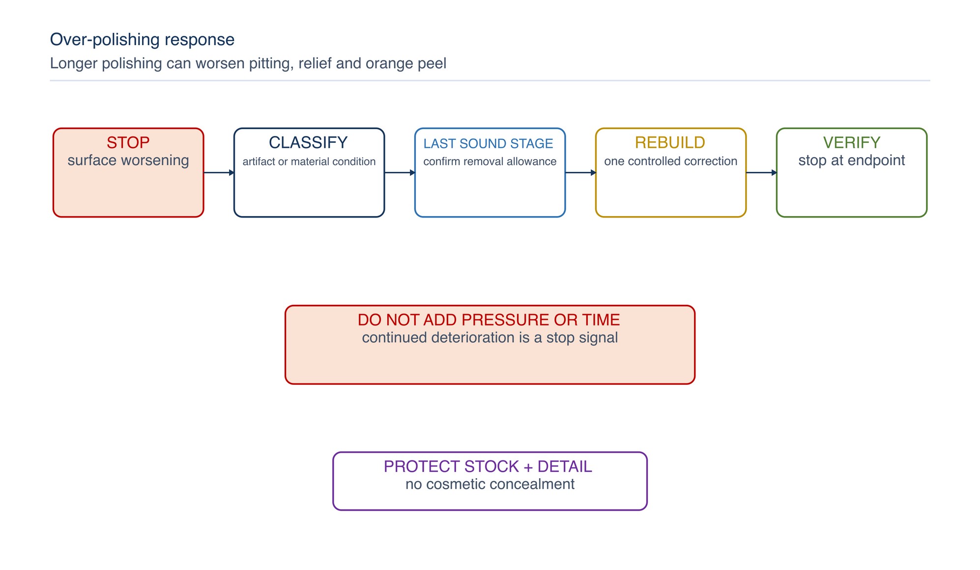
The response is:
- stop and preserve the observed pattern;
- confirm surface and geometry requirements;
- inspect material condition, media and machine;
- identify the last sound stage;
- establish whether further removal is permitted;
- restore a uniform base with one controlled correction;
- repeat only the necessary stages; and
- verify without extending polishing beyond the endpoint.
Heat tint, burn and distortion
Polishing can generate significant local heat through rubbing, loading, excessive dwell or unsuitable contact. Heat may affect coatings, hardness, residual stress, corrosion behaviour, dimensions or appearance.
Stop after unexpected thermal change. Visual removal of tint does not prove that thermal damage is absent. Review material and quality requirements before rework. Keep hot work, flammable compound, vapour and ignition controls active.
Machine, mop, pad and tool condition
Inspect:
- spindle, arbor and bearing condition;
- mounting security and runout;
- guard, extraction hood and work-rest arrangement where applicable;
- mop, pad, cloth or felt integrity and contamination;
- hard joints, exposed hardware or damaged edges;
- compound application condition;
- workholding and access; and
- electrical, pneumatic or drive performance.
Never improvise mounting parts or exceed the product or machine marking. Replace torn, hardened, contaminated or unstable media.
Control dust, fibres and combustible material
Polishing and buffing can release fine dust, fibres and compound residue. Provide effective capture and housekeeping for the actual material and process. OSHA ventilation guidance recognises local exhaust needs for polishing and buffing, while DOSH Malaysia has documented a combustible-dust explosion involving polishing machinery. [S008; S152; S310; S319]
Do not mix incompatible metal dusts or use ordinary vacuum equipment where combustible-dust controls require specialised equipment. Collector, duct, electrical classification, fire and explosion protection require competent design for the material and facility. NFPA 660 provides a current consolidated combustible-dust framework. [S325]
Verify correction and release
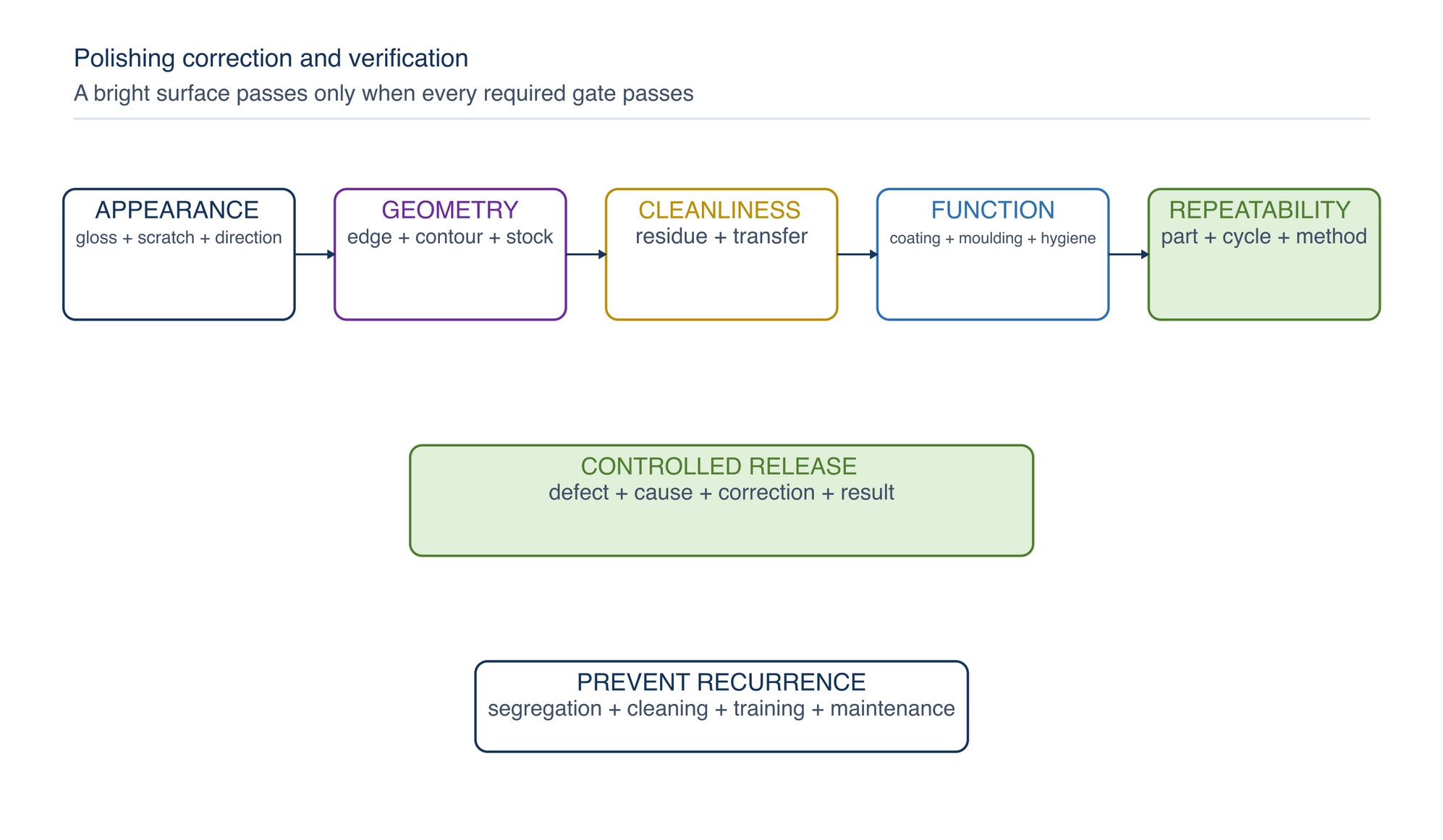
Verify as applicable:
- appearance under agreed lighting and orientation;
- absence of retained scratches, haze, drag lines and residue;
- specified texture measurement;
- flatness, contour, edges, dimensions and remaining section;
- cleanliness and freedom from prohibited transfer;
- coating, plating, hygiene, sealing or moulding readiness; and
- repeatability across more than one part or cycle.
Record the defect, confirmed cause, correction and result. Update media segregation, cleaning, training, machine maintenance or inspection control when recurrence risk remains.
Rapid troubleshooting table
| Symptom | Likely cause families | Controlled response |
|---|---|---|
| Deep retained line | incomplete base preparation | return to earliest effective stage and rebuild uniformly |
| Fresh random scratch | contamination, debris or damaged media | stop, clean system, replace contaminated media and reassess |
| Haze or low gloss | residue, incomplete prior pattern, variable contact | clean and inspect; restore uniform base if texture remains uneven |
| Patchy gloss or halo | local dwell, pressure or boundary mismatch | correct motion and refinish the controlled zone |
| Swirl or arc marks | rotary motion, edge contact, runout | restore mechanical truth and specified finishing direction |
| Smearing | rubbing, loading, incompatible media or compound | restore compatible cutting action and cleanliness |
| Relief or rounded edge | excessive compliance, time or local contact | protect geometry and reduce exposure to the cause |
| Pitting or pull-out | material constituents, porosity, corrosion or over-polishing | preserve evidence, assess cause, return to last sound stage if permitted |
| Orange peel | excessive final-stage work and material response | stop; rebuild from last effective preparation stage |
| Heat tint or burn | excessive heat input or loaded media | stop, assess surface integrity and correct thermal cause |
Concise safety reminders
- Inspect machine, guards, mounting and polishing media before use.
- Secure the component and maintain a stable position outside the ejection path.
- Tie back hair and control loose clothing, jewellery, gloves and rags around rotating machinery according to the safe work method.
- Use suitable eye, face, hearing, hand, body and respiratory protection.
- Capture dust and control combustible accumulations for the actual material.
- Keep compounds, cleaners and solvents away from incompatible heat and ignition sources.
- Isolate energy before cleaning, adjustment or media change.
- Treat cracking, pitting, burn and geometry loss as technical conditions, not merely visual defects.
Key takeaways
- Polishing depends on a uniform, damage-free base.
- Clean every interface when moving to a finer stage.
- Diagnose random scratches as contamination until the pattern proves otherwise.
- A brighter surface is not proof of geometry or surface integrity.
- Stop when orange peel, pitting or surface deterioration begins.
- Return to the earliest necessary stage rather than extending final polishing.
- Verify appearance, geometry, cleanliness and function separately.
Paint-Booth Filter Problems
The Paint-Booth Filter Problems chapter begins on the following page of the printed handbook (page 649), outside this chapter extract.