
Production engineers, welding supervisors, welders, grinding operators, inspectors, QA/QC personnel, safety personnel, trainers, maintenance teams and technical sales personnel
Controlled abrasive treatment of fillet, butt, lap and tack welds; stainless-steel, aluminium, structural and cosmetic welds; and internal and external weld locations. This chapter does not define weld acceptance, approve a weld repair, replace a welding procedure, authorise removal of parent metal or prescribe an MKTECH product, speed, angle, force, grit sequence, pass count, removal rate or finish value.
Weld grinding can remove design section, erase evidence of an imperfection, expose an internal discontinuity, change a fatigue-sensitive toe, contaminate a corrosion-resistant surface or create hazardous dust and sparks. Work only to a documented weld profile and inspection requirement. Use an identified abrasive on a compatible guarded machine, control dust, fire, hot work and nearby materials, and stop for unknown weld status, unknown material or coating, cracks, porosity, lack of fusion, unexpected cavities, parent-metal contact, undercut, heat tint, distortion, unstable work or any result outside the approved repair or finishing instruction. [S008; S009; S020; S032; S063; S076–S079]
Chapter objectives
After this chapter, the reader should be able to:
- distinguish weld-metal removal, toe blending, cosmetic finishing and weld repair;
- identify how fillet, butt, lap and tack geometry changes the accessible grinding route;
- recognise correct, under-ground, over-ground, undercut, thinned and excessively blended profiles;
- protect weld throat, root, toes, parent metal, coating and adjacent geometry;
- separate structural acceptance from cosmetic appearance;
- respond correctly when grinding reveals an imperfection;
- plan material-specific controls for stainless steel and aluminium; and
- create a traceable weld-grinding and inspection record.
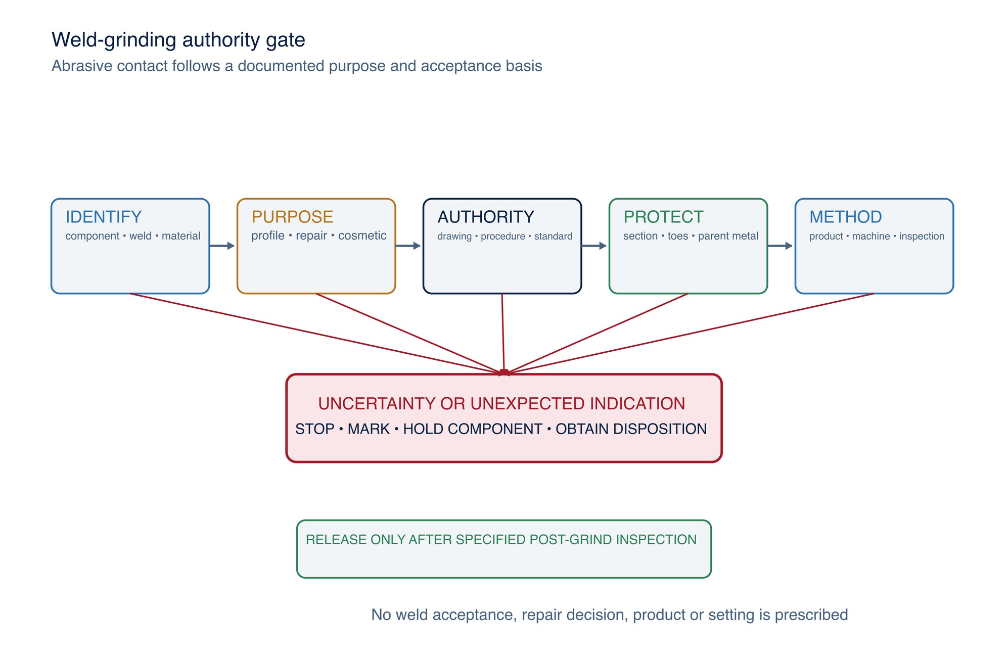
Acceptance comes before abrasive contact
A weld is not automatically approved for grinding merely because it is high, rough or visually uneven. Before work begins, identify why material is to be removed:
- to reach a specified weld contour or flush condition;
- to prepare an approved repair excavation;
- to remove a temporary attachment or tack under a controlled instruction;
- to create a smooth transition at a permitted weld toe;
- to remove surface oxide or contamination using an approved method; or
- to produce a defined cosmetic finish after structural acceptance.
The controlling drawing, weld procedure, fabrication specification, repair procedure and inspection plan determine what must remain. ISO 5817:2023 provides quality levels for imperfections in fusion-welded joints in steel, nickel, titanium and their alloys, while ISO 10042:2018 provides quality levels for aluminium arc welds. Their published scopes confirm that quality levels are application frameworks, not permission to grind every weld flush. ISO 17637:2016 establishes visual testing of fusion welds and can also apply before welding. [S076–S078]
Do not reproduce a limit from a different contract, material, thickness, weld class or service. The project specification and current controlled standard determine acceptance. Where the instruction is silent, hold the component and obtain an engineering or welding decision.
Weld type changes the grinding problem
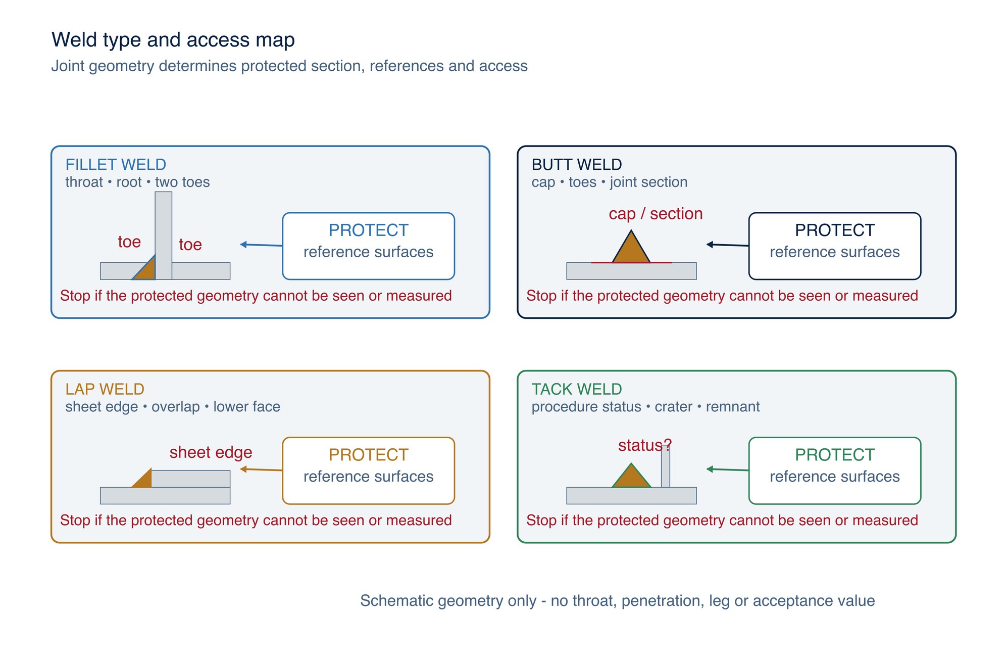
The joint geometry defines which surfaces carry load, which weld dimensions matter and which areas the abrasive can reach.
| Weld type | Geometry to protect | Typical grinding objective | Primary risk |
|---|---|---|---|
| Fillet weld | Effective throat, leg relationship, root region and both toes | Remove permitted excess, smooth a specified toe or create a documented contour | Throat loss, root thinning, toe undercut or gouging either parent surface |
| Butt weld | Joint section, cap, toes, root condition and alignment | Reduce a permitted cap, flush a specified surface or prepare an approved repair | Parent-metal thinning, hollow profile, hidden lack of fusion or loss of section |
| Lap weld | Sheet edge, upper and lower members, weld toe and overlap region | Remove spatter or blend a specified exposed edge | Cutting the sheet edge, opening the lap, thinning the lower member or trapping debris |
| Tack weld | Final-joint location, base surface and any crack-sensitive start/stop region | Incorporate, dress or remove only as the procedure allows | Tearing, crater cracking, local gouging or leaving an uninspected remnant |
Fillet welds
A fillet weld is not simply a triangular ridge to be flattened. Its usable section and toe transition belong to the joint design. Work from visible reference surfaces and inspect both toes repeatedly. If the root or throat cannot be verified from the grinding side, do not infer adequacy from appearance.
Butt welds
A butt-weld cap can be removed only when the required final profile allows it. Flush grinding should end at the specified surface reference without producing a trough across the joint or lowering adjacent parent metal. A smooth appearance does not prove fusion or penetration.
Lap welds
Lap joints combine an exposed sheet edge with a narrow transition. A broad abrasive can bridge the step and remove the upper edge; a narrow contact can dig into the lower member. Clean the overlap without driving debris into the joint and protect coatings that must remain.
Tack welds
Tacks can be part of the final weld, temporary attachments or fit-up aids. Their treatment belongs to the welding procedure. Never grind out a tack because it “looks temporary” without confirming its status, crack inspection and required surface restoration.
Profile language must be unambiguous
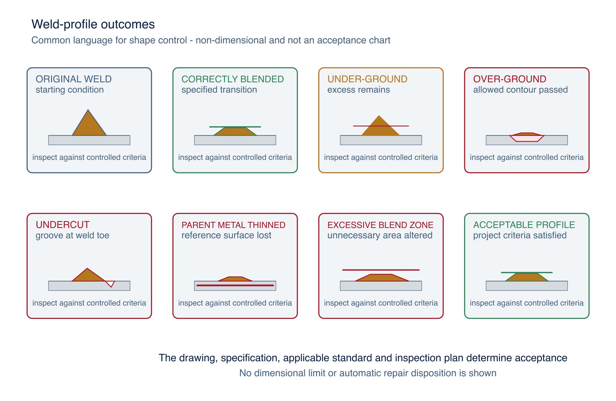
The words flush, blended, smooth and cosmetic are not interchangeable. A useful instruction defines the surface reference, permitted transition, protected section, inspection method and stop point.
Original weld means the as-welded profile presented for inspection or authorised processing.
Correctly blended weld means a controlled transition that meets the specified contour without removing protected weld or parent-metal section.
Under-ground weld means required excess, irregularity or transition remains.
Over-ground weld means abrasive removal has passed the allowed contour or section.
Undercut is a groove at a weld toe in the parent metal. TWI describes it as a geometric imperfection whose acceptability must be determined from the application standard or contract; blending or additional welding can be appropriate only in a controlled critical application. [S079]
Parent-metal thinning means the base material has been lowered below the approved reference or minimum remaining section.
Excessive blend zone means an unnecessarily wide or deep area has been altered, even if the centre of the weld appears smooth.
Acceptable profile means the completed and inspected profile satisfies the controlling requirement. It cannot be established from a generic illustration.
Grind in controlled phases
Phase 1 — Establish references
Clean and identify the weld, material and coating. Confirm the required contour, protected dimensions and inspection hold points. Mark boundaries where permitted and provide stable workholding, access, lighting and extraction. Photograph or record the starting condition when traceability or repair control requires it.
Phase 2 — Remove only authorised high material
Choose a product form that reaches the weld without forcing an undeclared abrasive edge, backing pad, hub or guard into adjacent surfaces. Keep contact on the weld crown or authorised excavation. Use repeatable travel and short inspection intervals. Do not pivot on a toe or dwell at a start/stop.
Phase 3 — Approach the stop reference
As the profile nears the reference surface, reduce the process intensity by moving to the approved controlled method—not by improvising with machine angle, pressure or unsupported product edges. Check contour from more than one direction. A highlight, spark pattern or smooth touch can conceal a hollow or step.
Phase 4 — Blend only where specified
Blend width is a controlled geometry, not a visual preference. Protect both parent surfaces, edges, holes, radii and nearby welds. On fatigue-sensitive details, the direction, smoothness and extent of toe treatment require an engineering-approved process.
Phase 5 — Clean and inspect
Remove abrasive residue using a material-compatible method. Conduct the specified visual, dimensional, surface-finish or non-destructive examination after grinding and at any intermediate hold point. Grinding does not close a weld inspection requirement; it creates a new surface that must be accepted. [S078]
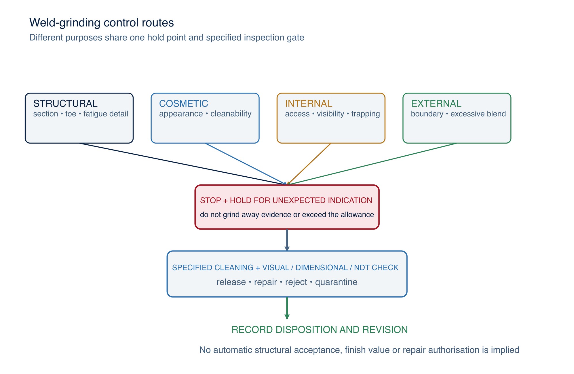
Structural and cosmetic work have different authorities
Structural weld grinding changes a load-carrying detail or its stress transition. The instruction must protect effective section and comply with the design, fabrication and repair controls. A smooth surface is not a substitute for a weld acceptance decision.
Cosmetic weld grinding targets appearance, hygiene, cleanability or a finish match. It still cannot reduce required joint section, conceal porosity or cracks, introduce cross-contamination or erase traceability. Cosmetic acceptance belongs after structural and repair acceptance unless the approved workflow explicitly combines them.
Internal welds often have restricted access, poor visibility and trapping risks. Confirm that the product, machine head and guard can enter and leave without touching an undeclared surface. Use inspection aids and stop when the root, toe or parent surface cannot be seen or measured adequately.
External welds offer more access but can encourage an unnecessarily wide blend. Establish visual and dimensional boundaries before work so the operator does not chase a uniform appearance across sound parent metal.
Material condition changes the controls
| Material or service | Additional control | Do not assume |
|---|---|---|
| Stainless steel | Segregated tools and abrasives, contamination control, heat-tint assessment and approved cleaning/passivation route | A bright surface is chemically clean, corrosion performance is restored or one abrasive sequence fits every grade |
| Aluminium | Confirm alloy, temper, section, loading/smearing behaviour, combustible-metal dust controls and separation from incompatible metal dust | Carbon-steel practice transfers safely, a loaded abrasive is cutting correctly or colour reveals temperature |
| Structural carbon or alloy steel | Confirm weld category, required profile, remaining section, toe treatment and post-grind inspection | Flush appearance proves adequacy or parent-metal loss can be accepted visually |
| Coated or galvanised work | Identify coating hazards, removal boundary and approved coating repair controls | Coating can be ground away without exposure or restoration |
| Hygienic or cosmetic service | Define finish direction, cleanability, contamination control and inspection lighting | Surface finish replaces weld integrity or an invisible blend is automatically acceptable |
Stainless-steel weld grinding may be followed by refinement, oxide removal, cleaning or passivation, but those are separate controlled operations. Worldstainless guidance treats heat tint, embedded contamination and surface treatment as corrosion-control matters; product-specific abrasive sequences remain conditional. [S001; S015; S016]
Aluminium can load an abrasive and produce fine combustible-metal dust. OSHA’s archived aluminium-grinding interpretation warns that heat and reaction risk depend on the complete material/process system and that aluminium and iron/steel dust interactions require control. Use a current local risk assessment and dedicated collection strategy; do not mix metal dust streams casually. [S009; S017; S020]
Grinding can reveal or create a repair condition
Stop immediately when abrasive removal reveals a crack-like indication, linear lack of fusion, clustered porosity, slag, an unexpected cavity, disbonded coating, severe undercut or a profile deeper than the authorised allowance.
Do not feather the indication until it disappears from view. That can enlarge the excavation, remove traceability and make the actual extent harder to establish. Mark and hold the component, preserve the location, notify the responsible welding/inspection authority and follow the approved excavation, examination and re-welding procedure.
TWI guidance distinguishes geometric imperfections from other discontinuities and notes that lack of fusion, penetration defects and porosity commonly require controlled removal to sound metal and re-welding. The exact repair route must follow the agreed welding procedure. [S079]
Controlled weld-grinding workflow
- Identify the component, weld number, material, thickness, joint type, location and service.
- Confirm weld acceptance status and the exact reason for abrasive work.
- Obtain the current drawing, fabrication specification, weld procedure, repair instruction and inspection plan.
- Define the target profile, protected section, parent-surface references, blend boundary and stop conditions.
- Verify machine, guard, mounting, speed compatibility, abrasive identity, working face and material suitability.
- Establish workholding, access, lighting, extraction, fire controls and contamination segregation.
- Record the starting profile and any pre-grind inspection result required by the plan.
- Remove authorised high material in short, repeatable passes while protecting toes, root and parent metal.
- Inspect at defined intervals and before changing product or process stage.
- Stop and quarantine for any unexpected indication or geometry loss.
- Clean with the approved material-specific method.
- Complete specified visual, dimensional, finish or NDT inspection and record disposition.
Troubleshooting by weld-profile signal
| Signal | Possible process cause | Controlled response |
|---|---|---|
| Weld remains high or transition remains sharp | Inadequate access, unsuitable product form, premature finishing stage or poor reference visibility | Hold; reassess access and authorised removal route; do not add uncontrolled force |
| Hollow across butt weld | Concentrated dwell, pivoting, narrow footprint or chasing local lows | Stop; measure remaining section and obtain disposition |
| Fillet toe or root is thinning | Contact crossed protected geometry or product cannot reach without side contact | Stop immediately; hold the joint for weld/engineering review |
| Blend zone keeps widening | No marked boundary, broad contact bridging the profile or appearance-driven rework | Restore a defined limit; inspect parent-metal level and finish |
| Pores or cavities appear | Internal discontinuity exposed during removal | Mark, hold and route to the approved weld-repair/NDT procedure |
| Surface smears, loads or overheats | Unsuitable or worn abrasive, poor cutting action, excessive dwell or wrong material controls | Stop; isolate affected output and verify the complete material–product–machine system |
| Stainless surface shows contamination or tint | Mixed tooling, embedded debris, excessive heat or incomplete cleaning route | Hold; apply the approved contamination and surface-restoration assessment |
| Aluminium dust accumulates or mixes with other dust | Inadequate segregation, collection or housekeeping | Stop work; isolate the hazard and correct the approved dust-control system |
Applying weld-grinding guidance
Define the required weld profile and inspection method before grinding. Select an abrasive declared for both weld and parent material, then work in controlled phases: establish reference surfaces, remove only authorised high material, approach the required contour gradually, blend where specified, clean and inspect.
Structural, cosmetic and hygienic welds can have different acceptance routes. Stop if grinding reveals cracks, lack of fusion, porosity, undercut beyond the stated limit or unexpected section loss; these conditions require the specified welding or quality disposition. Refer to the product label, Technical Data Sheet, or MKTECH representative.
Weld grinding and inspection record
For traceable work, record the component and weld ID, drawing and specification revision, joint type, material and thickness, location, service category, welding procedure, pre-grind inspection status, reason for grinding, target and protected profile, machine and guard, exact abrasive and batch, speed compatibility, support element, working face, angle/contact method, pass and inspection intervals, contamination and dust controls, dimensional and finish results, indications exposed, repair disposition, cleaning route and NDT result where required.
Heavy Stock Removal
The Heavy Stock Removal chapter appears on the following page of the printed handbook (page 112), outside this chapter extract.