
Production engineers, supervisors, operators, safety personnel, QA/QC personnel, maintenance teams, trainers, procurement staff and technical sales personnel
Application angle and contact-area control for depressed-centre grinding wheels, flexible grinding discs, flap discs and fibre discs on flat surfaces, edges, fillet welds, bevels, internal corners and external corners. This chapter does not approve an MKTECH product, angle, speed, force, pass count, removal rate, finish value or working method.
Angle is not an isolated setting. Use only the declared working face of an identified product on a compatible machine, guard, flange or backing pad. Follow the current manufacturer instructions for angle, speed, support and direction. Stop for missing markings, damaged products, guard or support interference, unstable work, loss of control, abnormal vibration, digging, edge breakage, glazing, excessive heat or any contact outside the declared use. [S032; S055; S063; S073]
Chapter objectives
After this chapter, the reader should be able to:
- distinguish application angle from contact area and effective load;
- recognise how product construction changes the permitted contact geometry;
- compare shallow, intermediate and steep approaches without treating them as universal degree settings;
- plan contact for flat grinding, edge work, fillet welds, bevel preparation and corners;
- identify angle-related signals such as digging, glazing, excessive wear, heat and poor finish;
- create a repeatable angle/contact trial and approval record; and
- stop when product identity, compatibility or operating instructions are unclear.
Angle controls the contact system
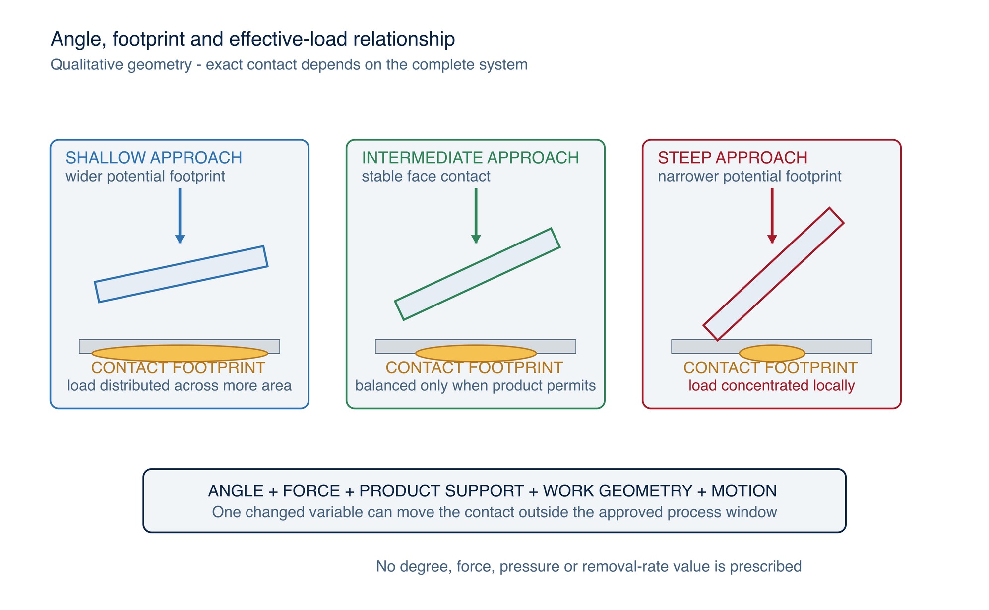
Application angle is the orientation of the abrasive’s declared working face relative to the local work surface. Contact area is the portion of that face carrying load at a particular moment. The two are related, but they are not interchangeable.
A change in angle can move contact toward an edge, reduce or widen the footprint, change how stiffly the product presents itself, and alter the direction in which the machine reacts. The same nominal angle can create a different footprint when product diameter, wear, backing-pad stiffness, wheel profile, work curvature, pressure or operator motion changes.
The practical control is therefore not “hold one number.” It is to verify the product family and working face, establish a stable contact footprint on representative work, control force and motion, and inspect the result. [S032; S055; S073]
Contact area changes load concentration
For a given applied force, a smaller effective footprint concentrates load into a narrower region. A wider footprint distributes load across more abrasive and more work surface. This is a qualitative relationship, not a pressure calculation: real contact is uneven and changes as abrasive grains cut, the product flexes and the work geometry moves.
A narrower footprint can:
- increase local cutting intensity and geometry sensitivity;
- make edge digging, gouging or undercut more likely;
- raise local heat input when motion or cutting action is poor; and
- accelerate local product wear.
A wider footprint can:
- spread force and support smoother blending;
- reduce access to narrow features;
- increase total rubbing area if the abrasive is loaded or the force is too low; and
- make guard, pad or hub clearance more important.
Neither narrow nor wide contact is automatically correct. The accepted footprint is the smallest controlled contact that performs the defined task without violating the product’s declared working face, damaging adjacent geometry or creating unacceptable heat, finish or wear.
Product family determines the permitted approach
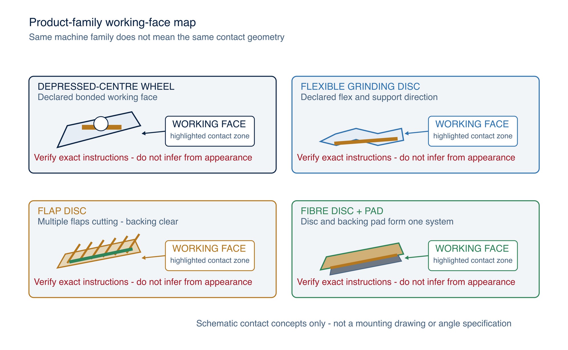
Product construction controls how contact is supported. A depressed-centre bonded wheel, a flexible grinding disc, a flap disc and a fibre disc may fit a right-angle machine, but they do not share one working face, stiffness, backing requirement or angle instruction. Treat each as a distinct construction and verify wheel type, dimensions, reinforcement, declared use, guarding and maximum operating speed on the exact product. [S055; S073]
| Product family | Contact structure | Controlled angle principle | Stop condition |
|---|---|---|---|
| Depressed-centre grinding wheel | Rigid bonded body with a declared grinding face | Keep contact on the permitted face and inside the manufacturer’s angle range; do not lever or side-load an undeclared surface | Hub/guard interference, edge-only contact, wheel chatter, glazing, digging or damage |
| Flexible grinding disc | Flexible abrasive body or reinforced construction intended to conform within limits | Use only the declared support and flex direction; avoid folding, creasing or concentrating load at an unsupported edge | Excessive flex, crease, backing exposure, delamination, snagging or unstable contact |
| Flap disc | Overlapping coated-abrasive flaps carried on a shaped backing | Match flat or conical construction to the task; maintain enough face contact for multiple flaps to cut without loss of shape | Backing contact, flap tearing, severe bounce, local burn or striking the backing |
| Fibre disc | Coated-abrasive fibre disc supported by a backing pad | The pad and disc form one contact system; keep the supported abrasive face engaged and avoid exposing the disc edge or pad | Pad contact, disc edge catch, centre interference, tear, heat distortion or loss of support |
Depressed-centre grinding wheels
The wheel is comparatively rigid. Tilting changes which part of the declared grinding face carries load and how strongly the wheel edge enters the work. Too shallow an approach can encourage rubbing or hub/guard interference on some configurations. Too steep an approach can narrow the footprint, increase digging and create side loading that the product was not intended to carry. Never infer permitted side grinding from reinforcement, wheel shape or past practice. [S032; S073]
Flexible grinding discs
Flexibility can help the abrasive follow a blend or contour, but flex is not unlimited. Support, disc construction and rotation direction control how the face enters the work. Excessive deflection can crease the body, expose the backing, overheat a small region or allow the edge to catch.
Flap discs
Flap-disc profile changes presentation. A flatter construction generally presents its face differently from a conical construction. The controlled objective is to keep several flaps cutting with stable overlap while preventing the backing from touching the work. A steeper approach is not a substitute for a product profile suited to the feature.
Fibre discs
The backing pad defines stiffness, support and local conformity. The disc cannot be evaluated separately from the pad. Excessively shallow or offset contact can bring the pad or centre into the work; concentrated edge contact can catch or tear the disc. Verify pad diameter, hardness, attachment, speed rating and condition with the exact fibre disc.
Geometry changes the local reference surface
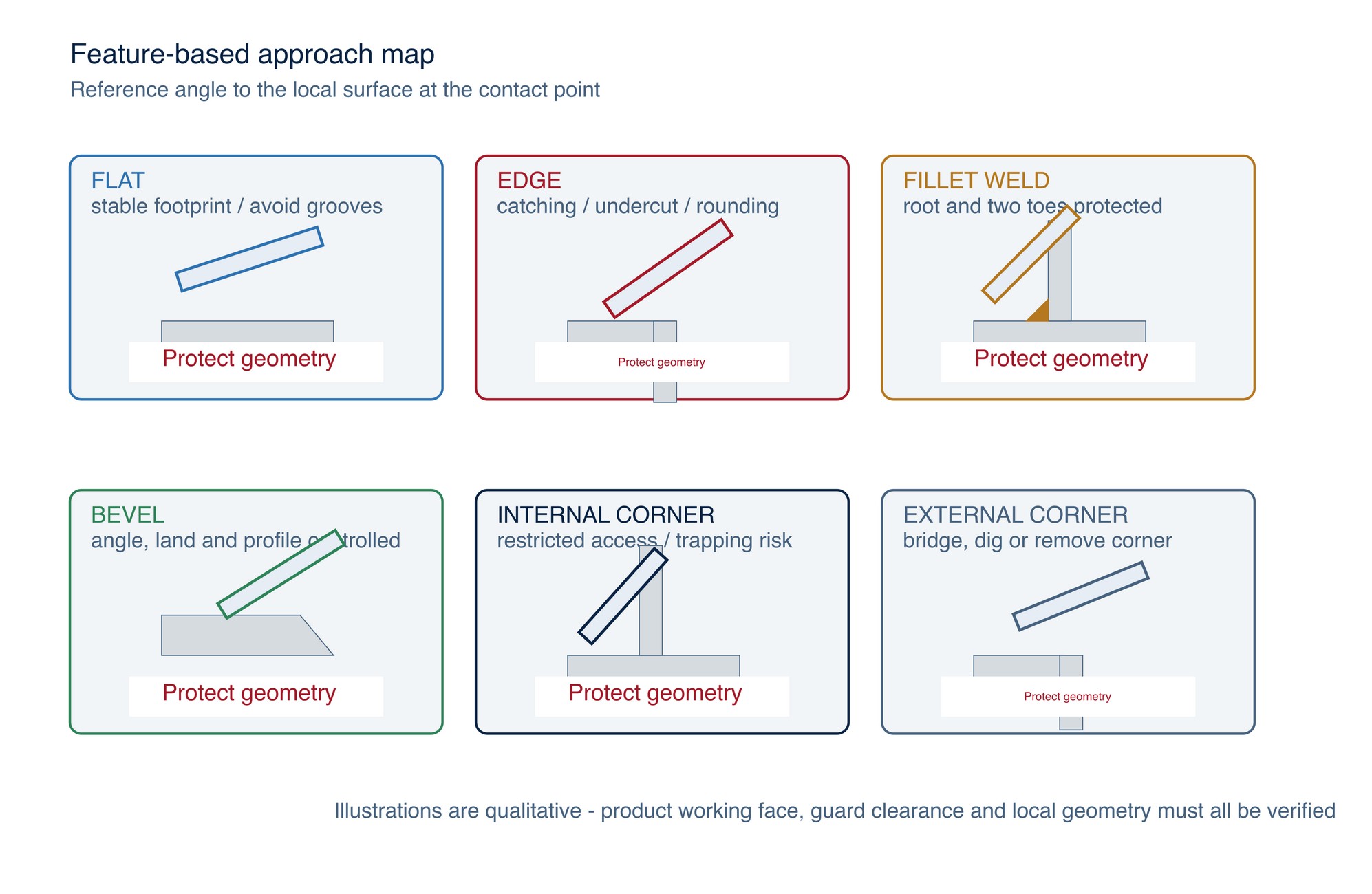
“Angle to the work” must be measured against the surface at the contact point, not against the floor, bench or overall part. Curves and corners change that local reference continuously.
Flat grinding
Flat work offers the largest opportunity for a stable footprint. Approach so the declared abrasive face contacts before the hub, backing pad or guard can interfere. Use overlapping motion and maintain the product in a plane that does not introduce unintended grooves. Verify flatness or blend acceptance with suitable inspection rather than judging only spark pattern.
Edge grinding
An edge creates a narrow support line and a high risk of catching, chipping, undercut or excessive rounding. Control the direction of rotation and travel so the abrasive cannot climb unpredictably onto or off the edge. Do not let the product’s unsupported edge perform work unless the exact product is declared for that use.
Fillet welds
A fillet joins two surfaces and limits access near the root and toes. The contact must remove the defined weld or transition without gouging either parent surface or thinning the root. Choose a product form that can reach the feature while keeping its declared face supported. Work from controlled reference surfaces and inspect both sides of the fillet.
Bevel preparation
Bevel grinding creates geometry, not merely material removal. The abrasive approach must support the required bevel angle, root face and land without rounding the edge or introducing a hollow profile. Use gauges or templates suitable for the joint design. Do not attempt to “correct” bevel geometry by increasing force or steepening the abrasive after the process drifts.
Internal corners
Access is restricted and adjacent surfaces can trap the product or force guard interference. Confirm that the product diameter, profile and machine head can reach the feature without contacting an undeclared face. Short, controlled contact and frequent inspection are preferable to blind pressure into the corner.
External corners
The local surface direction changes abruptly across the corner. A wide footprint can bridge and round the corner; a narrow footprint can dig into one face or cut the corner away. Define whether the corner must remain sharp, receive a controlled radius or be blended, then protect the adjacent faces accordingly.
What changes when the angle changes
| Observed change | Contact mechanism | Possible process result | Controlled response |
|---|---|---|---|
| Footprint becomes narrower | Load moves toward a smaller part of the abrasive face | Faster local cutting, digging, grooves, local heat or rapid wear | Reduce contact intensity; restore the approved face and motion |
| Footprint becomes wider | More abrasive and work surface share the load | Smoother blend or increased rubbing/heat if cutting action is weak | Verify product condition, force, motion and support |
| Product becomes effectively stiffer | Geometry or support reduces conformity | Stronger shape generation but less forgiveness | Protect adjacent geometry; inspect more frequently |
| Product becomes effectively more flexible | Face or pad follows the work more closely | Better blending but possible rounding or loss of dimensional control | Use reference surfaces, templates or gauges |
| Reaction direction changes | Tangential force acts through a different contact point | Pull, push, climb, bounce or loss of control | Stop; correct stance, workholding, rotation/travel and approach |
| Edge or backing enters contact | Working face is lost or support is exposed | Snagging, tearing, gouging, backing damage or ejection hazard | Stop and quarantine damaged product; correct the configuration |
Angle interacts with force. If the footprint narrows while the applied force remains similar, local load rises. If the footprint widens without enough cutting action, the system may rub. Adding pressure is not a valid response to glazing, loading or weak cutting until product condition, material suitability, speed, contact and machine response have been verified. [S071; S075]
Heat, wear and finish signals
Heat is generated by cutting, ploughing and friction. Angle can shift the balance by changing footprint, grain engagement and motion. Discolouration, resin odour, backing distortion, rapid wheel wear, local glazing or a polished track can signal that contact is no longer controlled.
Finish quality also records contact history. Deep isolated scratches, scallops, directional grooves, edge rounding and an uneven blend often indicate changes in angle, dwell, travel path, abrasive condition or support. Inspect the surface under consistent lighting and use the specified dimensional or finish method where acceptance depends on geometry or roughness.
Product wear changes contact geometry over time. A bonded wheel becomes smaller and its edge profile changes. Flaps shorten and can expose the backing. Fibre discs lose abrasive and may soften or distort. The approved process therefore needs a change-out rule based on product condition and output, not only elapsed time.
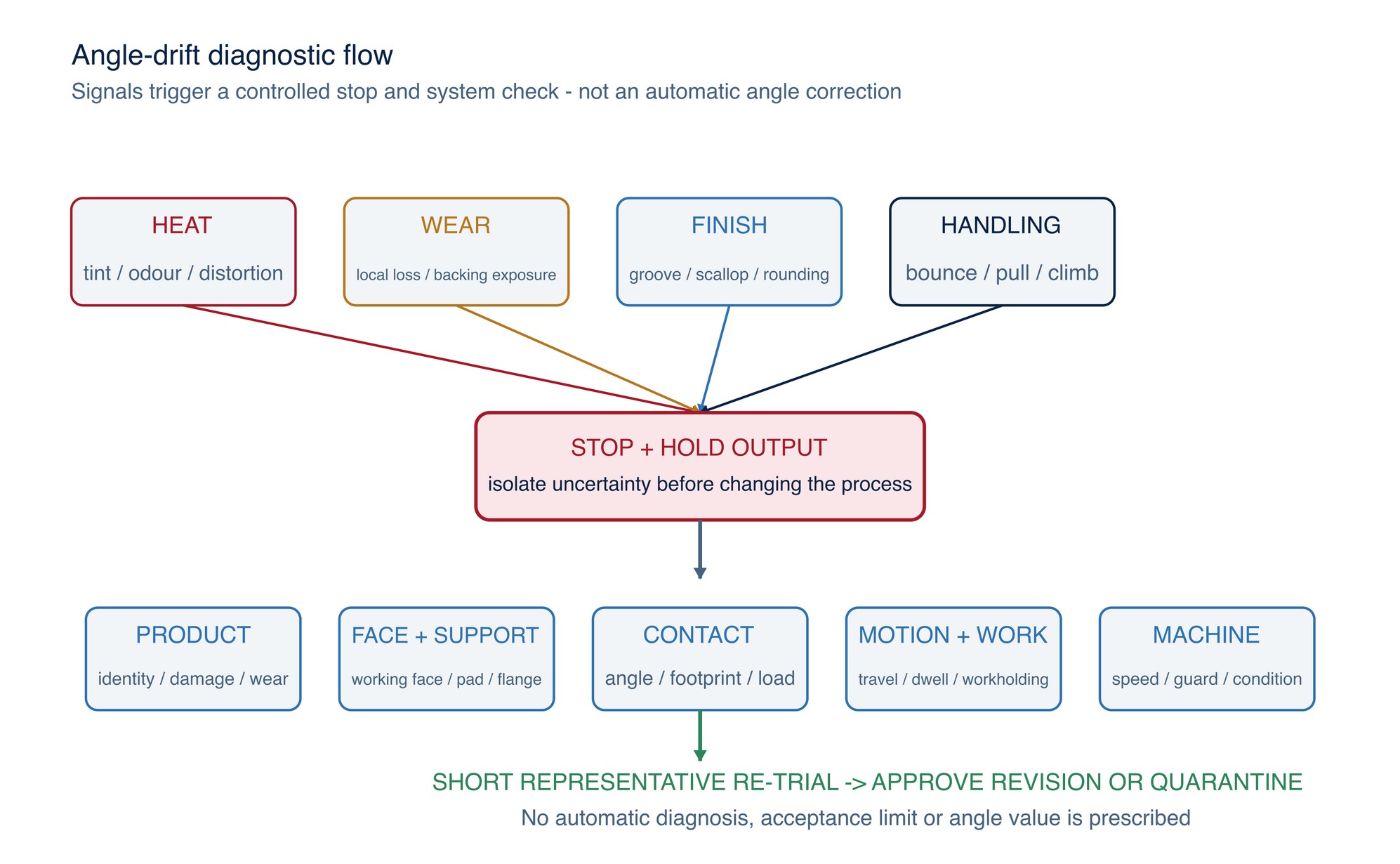
Controlled setup and trial
- Define the material, feature, stock allowance, protected geometry and accepted output.
- Identify the exact abrasive, declared working face, support element, machine, guard and speed range.
- Obtain the current manufacturer angle and application instructions.
- Mark or fixture reference surfaces where geometry must be preserved.
- Secure the work and establish a stance or programmed path that controls reaction direction.
- Begin with stable face contact and the lowest effective load within the approved method.
- Use repeatable travel, overlap and dwell; do not pivot on one point.
- Inspect geometry, heat, scratch pattern, product wear and handling response after short intervals.
- Adjust only one controlled variable at a time.
- Record the approved product–machine–feature–angle–load–motion revision.
For automated work, the record must also define tool orientation, path frame, commanded force or displacement, compliance device, approach/retract behaviour, workholding, sensing, wear compensation and fault response. A programmed angle does not prove the actual contact angle when part location, wheel wear, compliance or robot stiffness changes. [S070]
Troubleshooting by contact signal
| Signal | Possible angle/contact causes | Controlled response |
|---|---|---|
| Digging or gouging | Footprint too narrow, excessive dwell, steep entry, unstable edge contact | Stop; protect the part; restore supported face contact and re-trial |
| Glazing or polished track | Rubbing, weak effective load, wrong face, unsuitable product or speed response | Stop; inspect product and system; do not add uncontrolled pressure |
| Rapid local wear | Concentrated contact, edge loading, excessive force or unsuitable product profile | Hold output; verify angle, support and product suitability |
| Heat or discolouration | Excess dwell, rubbing, wide loaded contact, poor motion or weak extraction/cooling | Stop; isolate affected output; correct and revalidate |
| Bounce, pull or climb | Reaction direction, entry path, workholding or product damage is uncontrolled | Stop; secure work and reassess rotation, travel and approach |
| Rounded edge or lost bevel | Footprint bridges the feature, product conforms excessively or inspection is too late | Restore reference control; use gauges and shorter inspection intervals |
| Backing, pad or hub marks | Product face is no longer the only contact surface | Stop immediately; inspect and quarantine damaged parts |
Applying angle and contact guidance
Begin with the working face and angle permitted for the exact product. Keep the guard and support system correctly positioned, approach the work under control and use the smallest contact area that remains stable for the required operation. Maintain consistent travel and avoid edge digging, side loading, excessive dwell and angle drift.
Watch the process signals together: cut, spark pattern, sound, vibration, heat, scratch shape, product wear and geometry. A change in one signal is a reason to inspect the complete system before applying more force. Refer to the product label, Technical Data Sheet, or MKTECH representative.
Angle and contact setup record
For repeatability, record the task, material, feature, protected geometry, allowance, required output, machine and speed, guard, exact abrasive and batch, product profile, declared working face, flange/hub/pad, manufacturer angle instruction, selected angle where measurement is required, contact-width reference, load method, travel direction, overlap, dwell control, workholding, inspection intervals, heat, finish, geometry results and product wear.
Weld Grinding
The next chapter, Weld Grinding, begins on the following page of the printed handbook, outside this chapter extract.