
Production engineers, supervisors, operators, maintenance teams, safety personnel, QA/QC personnel, procurement staff, automation engineers and technical sales personnel
Angle, straight, die, bench, pedestal and belt grinders; automated and robotic grinding systems; pneumatic, electric and variable-speed drives; and the control of power, torque, RPM, spindle, diameter, guarding, flanges, vibration, maintenance and machine-product compatibility. This chapter does not approve an MKTECH machine, abrasive SKU, operating speed, pressure, air setting, power rating, guarding arrangement, robot path or production result.
A machine name or power rating is not permission to mount an abrasive. Verify the complete machine, abrasive product, dimensions, spindle or collet, flange or support element, guard, maximum permitted speeds, energy supply, work material, operation and current instructions. Isolate energy before adjustment or maintenance. Stop for missing identification, damaged parts, abnormal vibration, incorrect guard or interface, uncontrolled dust/sparks, unstable workholding or any condition outside the declared use. [S032; S063; S069]
Chapter objectives
After this chapter, the reader should be able to:
- distinguish the main grinder and power-tool families by load path and access;
- interpret power, torque and RPM without treating any one value as performance proof;
- verify spindle, collet, flange, pad, contact wheel, diameter and guard compatibility;
- compare electric, pneumatic and variable-speed drive implications;
- recognise vibration and maintenance as system-control issues;
- separate automated machinery from a validated robotic grinding cell; and
- create a controlled machine-product compatibility record.
The machine is one part of the abrasive system
A grinding result is created by a chain: energy supply, motor, transmission, spindle, mounting interface, abrasive product, contact zone, work support, extraction and operator or automation control. A strong motor cannot correct a wrong flange. Variable speed cannot make an unapproved product safe. A robot cannot compensate for an unstable process unless the cell is designed, sensed, guarded and validated for the variation.
Machine selection should therefore begin with the task: material, action, stock allowance, geometry, access, accepted surface, production volume and hazards. It then narrows through machine architecture and interface before any exact abrasive is released.
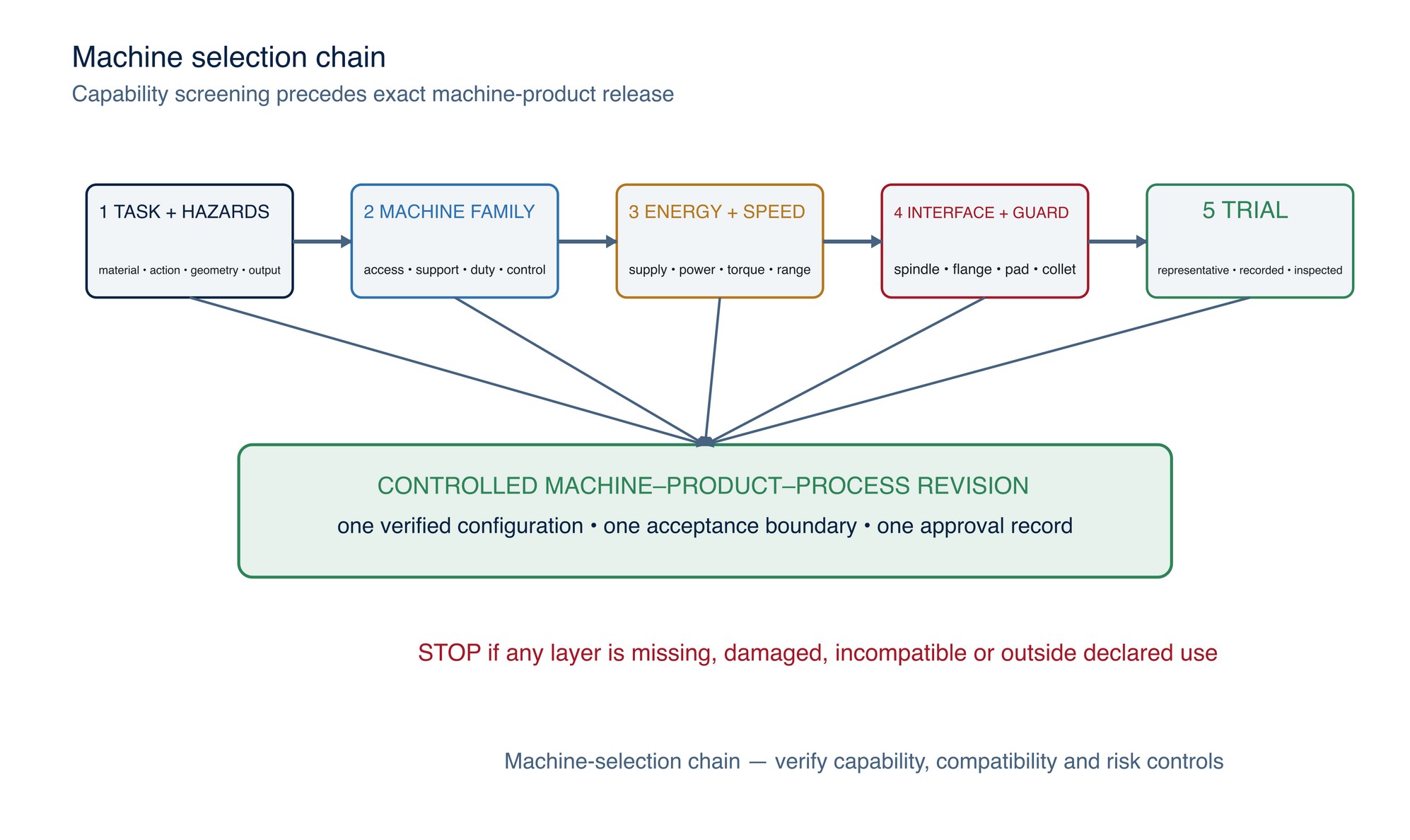
Machine-family comparison
| Characteristic load path and access | Machine family | Typical controlled role | Principal verification points |
|---|---|---|---|
| Motor axis turns through a right-angle head to a side-access spindle | Angle grinder | Cutting, grinding, blending, sanding and conditioning on accessible faces and edges | Product type, diameter, spindle thread, backing pad/flange, side handle, guard type, speed and working face |
| Motor and spindle share a common axis; larger or slower arrangements may carry wheels or arbors | Straight grinder | Straight-line access, internal or external grinding, deburring and polishing | Arbor or spindle, wheel/flange arrangement, guard, overhang, balance and rated speed |
| Compact straight or angle head, usually using a collet and shank-mounted tool | Die grinder | Bores, grooves, fillets, radii, small moulds, local deburring and shape correction | Collet size and condition, shank, clamping depth, unsupported length, runout, speed and engagement |
| Fixed machine mounted to a bench; operator presents the work to the wheel | Bench grinder | Tool-room grinding, deburring and controlled offhand work | Wheel and flange, guard, tongue/spark control, work rest, mounting, wheel condition and work support |
| Floor-mounted fixed grinder, often larger or more heavily used than a bench unit | Pedestal grinder | Foundry, fabrication and maintenance grinding with supported work | Foundation, wheel/flange, guard openings, adjustable work rest, extraction, work handling and exposure time |
| Endless abrasive belt runs over drive/idler wheels and a platen, contact wheel or slack section | Belt grinder | Stock removal, weld blending, flat finishing, edge work and contour finishing | Belt size/direction, tracking, tension, platen/contact wheel, guarding, dust collection, speed and work support |
| Purpose-built machine executes a defined cycle with controlled work and tool motion | Automated grinding machine | Repetitive stock removal, edge finishing or surface generation | Machine guarding, interlocks, workholding, axes, tool wear compensation, inspection, hazardous energy and change control |
| Programmable robot moves the part or abrasive within an integrated cell | Robotic grinding system | Variable geometry, multi-face processing, deburring, blending and finishing | Risk assessment, payload, reach, stiffness, end-of-arm tooling, force/vision sensing, ancillary equipment, guarding, interlocks and validated program |
These families overlap. A right-angle machine may drive a bonded wheel, flap disc, fibre disc or non-woven product, but each format can require a different guard and support. A belt grinder may be hand-guided, fixed or integrated into a robot cell. Select by the complete configuration, not the family label.
Power, torque and RPM
Power describes the rate at which mechanical work can be delivered. Torque is rotational turning effort. RPM describes rotational speed. In an ideal rotating system, mechanical power equals torque multiplied by angular speed. Real machines also have losses, controls and thermal limits.
Three controls follow:
- A higher input-power number does not establish greater abrasive removal on the work. Transmission efficiency, available torque under load, product geometry, contact area, abrasive sharpness and operator control all intervene.
- No-load RPM is not the same as speed under grinding load. Excessive speed drop may indicate overload, insufficient supply, a worn machine or an unsuitable process; the response is to stop and diagnose, not press harder.
- Product speed compatibility is a safety boundary. The machine's possible speed must not exceed the abrasive product's maximum permitted speed, and the product must also be suitable for the intended operating range and diameter. [S032; S063]
Abrasive surface speed also changes with diameter. At the same RPM, a larger diameter produces a higher peripheral speed. As a wheel wears smaller, peripheral speed falls unless an approved controlled-speed system compensates. Motor speed, wheel wear and abrasive change are therefore linked factors in automated abrasive performance. [S070]
Variable speed: a controlled process window
Variable speed is useful when approved products or process stages require different operating ranges. It can help manage smaller diameters, heat-sensitive finishing stages, brushes, pads and other product-specific needs. It does not authorise low-speed use of a product whose stability, support or cutting behaviour is unsuitable there.
An angle-grinder specification normally includes rated input power, declared no-load speed range, spindle interface and the specified guard, flange and handle. These characteristics must be checked on the exact machine rather than generalised across angle grinders. [S066]
For each released stage, record:
- the machine identity and available speed range;
- the exact abrasive product and permitted speed range;
- diameter and resulting interface configuration;
- approved selected setting and method of verification;
- response under normal load;
- material, geometry and thermal/finish acceptance; and
- who authorised the revision.
Spindle, collet, flange and support compatibility
Mounting components transmit torque and position the product. They are safety-critical machine parts, not generic accessories.
| Interface | Required match | Common invalid assumption |
|---|---|---|
| Threaded spindle or hub | Thread form, diameter, direction, seating face, product type and manufacturer instructions | “It threads on, so it fits” |
| Collet and shank | Nominal sizes, clean undamaged surfaces, insertion/clamping requirement, runout and permitted overhang | Tightening can correct a worn collet or undersized shank |
| Wheel flanges | Correct matched pair, diameter, relief, seating surfaces, blotters where required and tightening method | Any washer or nut can replace the specified flange |
| Backing pad | Product diameter, attachment, hardness/flexibility, rated speed, centre system and guard clearance | A softer or harder pad changes only comfort |
| Belt contact element | Belt size, tracking/tension range, platen/contact-wheel geometry and speed | The belt alone determines flatness or conformity |
OSHA's abrasive-wheel rule requires grinding machines within its scope to use specified safety guards and flanges, and it treats work rests and exposure openings as controlled features. FEPA likewise places dimensions, maximum operating speed, machine condition and correct mounting at the centre of abrasive safety. Local Malaysian applicability must be confirmed against current law and the employer's risk controls. [S032; S062; S063]
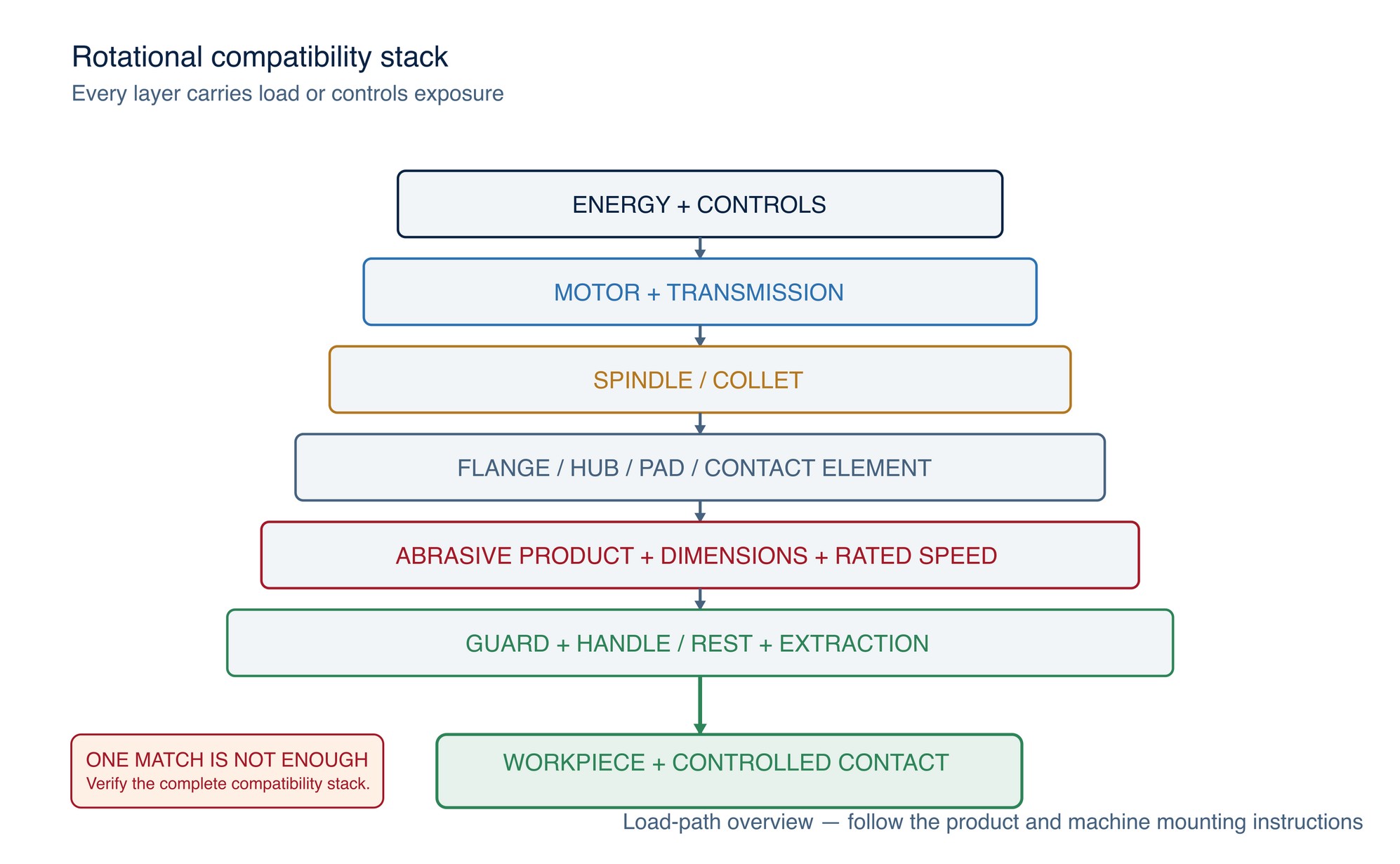
Guarding, flanges and fixed-machine work support
A guard must be the type and configuration required for the machine, abrasive and operation. It should be correctly aligned, securely mounted and positioned so the intended working area is available without exposing more of the product than allowed. A spark shield, visor or extraction hood does not automatically replace an abrasive-wheel guard.
For bench and pedestal grinding, the work is presented to the rotating wheel. The work rest therefore controls support and the gap where work could become trapped. OSHA 1910.215 specifies a closely adjusted, securely clamped rest and prohibits adjustment while the wheel is moving; it also controls guard exposure and flange arrangements. These numeric US provisions are not copied into an MKTECH operating instruction. The exact current Malaysian requirement, machine manual and site risk assessment govern local use. [S063]
Stop the fixed machine when:
- the wheel, belt, flange, guard, rest or mounting is damaged or uncertain;
- the rest, guard opening or contact element cannot be maintained as required;
- tracking, runout, noise or vibration changes;
- work cannot be held and supported without the hands entering the hazard zone;
- sparks, dust or fragments are not contained and extracted; or
- isolation cannot prevent unexpected start or stored-energy movement.
Electric and pneumatic drives
The choice between electric and pneumatic drive is a system choice, not a universal ranking.
| Drive | Useful considerations | Dependencies and controls |
|---|---|---|
| Corded electric | Continuous supply without battery change; broad power and speed-control options | Rated supply, cable/plug condition, electrical protection, restart control, overload behaviour and dust/environment suitability |
| Battery electric | Mobility and no trailing mains cable at the contact area | Approved battery/tool system, charge state, thermal control, restart behaviour, battery damage and task duration |
| Pneumatic | Compact power unit, high speed options and suitability for established compressed-air systems | Pressure and flow at the tool, hose/coupling size, filtration, water control, lubrication where required, exhaust, noise and compressor capacity |
Pneumatic grinder performance depends on regulated air pressure, supply condition and lubrication requirements. Straight and die grinders also differ by speed, collet, inlet and hose characteristics. Verify every field at the exact tool rather than generalising across pneumatic machines. [S067; S068]
For either energy source, a falling speed under load does not justify additional force. Check the process demand, product condition, supply, filters, cables, batteries, air lines and tool maintenance against current instructions.
Vibration and operator exposure
Vibration is both a health exposure and a condition signal. HSE identifies hand-held grinders, sanders and pedestal grinding among processes that can expose hands and arms to vibration. Its control guidance prioritises alternative methods, suitable efficient lower-vibration equipment, maintenance, workstation design, training and exposure-time management. It warns that unsuitable or under-powered equipment can prolong the job and exposure. [S064; S065]
Do not compare declared emission numbers as if they guarantee actual exposure. Work material, abrasive balance, product wear, bearings, contact force, posture, grip, duty cycle and maintenance affect the task. A changed vibration signature can indicate damage, imbalance, runout, loose mounting, bearing wear, incorrect contact or belt-tracking problems.
The controlled response is:
- Stop for sudden or unexplained vibration, noise or handling change.
- Isolate the machine and inspect the permitted items.
- Quarantine damaged or uncertain abrasive and mounting parts.
- Correct the process or arrange competent maintenance.
- Reassess exposure and health-surveillance requirements through the employer's occupational-safety system.
Maintenance and pre-use control
Maintenance preserves both safety and process capability. HSE recommends appropriate maintenance to prevent avoidable vibration increases and to keep consumables efficient. [S065]
Before use: confirm machine identity, controls, guard, handle, spindle/collet/flanges, support element, supply, cables/hoses, extraction, workholding and abrasive condition. Perform only the checks authorised by the machine and product instructions.
During use: monitor speed response, vibration, noise, temperature signals, tracking, sparks, dust, workpiece stability and surface condition. Do not defeat a guard, interlock, restart control or extraction device to continue production.
After use: isolate energy, allow rotation to stop, clean by an approved method, inspect for damage, record defects and store the tool and abrasive to prevent contamination and impact.
Planned maintenance: use competent personnel, manufacturer intervals, approved parts and recorded post-maintenance verification. Maintenance must cover safety functions as well as bearings, brushes, lubrication, air treatment, belts, cables, guards and fasteners.
Automated machines and robotic grinding cells
Automation repeats a process; it does not automatically make the process controlled. A purpose-built automated machine generally constrains axes, tooling and workholding around a defined cycle. A robot offers programmable reach and orientation but requires an integrated cell whose risks, payload, stiffness, sensing, tooling and safeguards are designed together.
OSHA's robotics guidance points to machinery guarding, hazardous-energy control and industrial-robot risk assessment and safeguarding standards. Cell design must also address ancillary equipment, payload, motor power and speed, abrasive change, sequence, dust collection, force control, re-gripping and operator safety. [S069; S070]
Force control can help manage part and abrasive variation, but it is not a substitute for stable workholding or an approved process window. Vision may locate or inspect parts; temperature sensing may support heat control. Each sensor requires defined accuracy, failure response and validation.
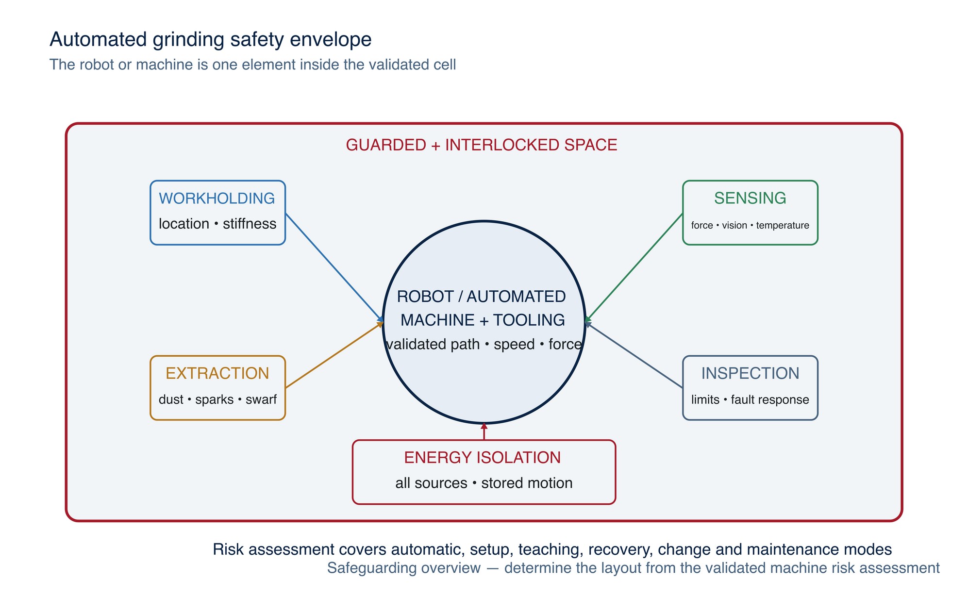
Cell release must include:
- risk assessment for automatic, setup, teaching, recovery, abrasive change, cleaning and maintenance modes;
- safeguarded space, access control, interlocks, emergency stops and safe restart;
- hazardous-energy isolation for every energy source and stored motion;
- validated payload, reach, speed, path, stiffness, force and workholding;
- abrasive identity, wear/change rule and machine-product compatibility;
- extraction, spark, fire, swarf and noise controls;
- inspection method, process limits and fault response; and
- controlled program, tooling and parameter revision history.
Machine-product compatibility workflow
- Define the material, action, geometry, access, allowance and accepted output.
- Select a machine architecture capable of reaching and controlling the contact zone.
- Verify energy supply, power/torque behaviour and approved speed range under the task.
- Match exact product type, dimensions, rated speed and intended working face.
- Match spindle/collet, flange/hub/pad/contact element and permitted mounting method.
- Match guard, handle, rest, workholding, extraction and environment controls.
- Inspect machine, interface and abrasive condition; stop for uncertainty.
- Conduct a representative trial with defined load, exposure and acceptance limits.
- Record results and release one controlled machine-product-process revision.
Troubleshooting by system signal
| Signal | Possible system causes | Controlled response |
|---|---|---|
| Speed collapses under normal contact | Excess load, unsuitable abrasive, weak supply, blocked air path, low battery, motor or transmission fault | Stop; verify task, supply and tool condition; do not add pressure |
| Vibration or noise changes | Damage, imbalance, runout, loose mounting, worn bearing, belt tracking or unstable work | Isolate; quarantine uncertain parts; inspect and maintain |
| Repeated guard or rest interference | Wrong product, diameter, flange, pad, guard or setup | Stop; correct the complete approved configuration |
| Heat or finish drifts | Worn/loaded abrasive, changed speed/force/contact, weak extraction/cooling or work variation | Hold output; restore the controlled process and revalidate |
| Robot path or force becomes inconsistent | Part location, workholding, tool wear, payload, sensor, program or mechanical stiffness change | Stop cell; enter controlled recovery; inspect revision and sensing |
Pairing the machine and abrasive in practice
Treat the machine, abrasive and mounting system as one assembly. Confirm the machine type, spindle or collet, speed range, permitted diameter, guard, flanges, hub, backing pad or contact element, power source and current condition. The abrasive must be declared for the intended operation and every interface must match without improvised adapters.
For pneumatic tools, verify regulated pressure, flow, hose and lubrication requirements; for electric tools, verify supply, cable or battery condition and restart control. Investigate abnormal vibration, speed loss, heat or noise before continuing. Follow the current machine instructions. Refer to the product label, Technical Data Sheet, or MKTECH representative.
Machine-product setup record
For repeatability and maintenance traceability, record the task, material, geometry, machine model or asset number, energy source, power, speed range and selected setting; spindle or collet; flange, hub, pad or contact element; product code, type, dimensions and rated speed; guard, handle, rest or workholding; extraction; vibration information; inspection status; maintenance revision; operator or automation program; and output inspection result.
Grinding-Wheel Selection
The Grinding-Wheel Selection chapter appears on the following page of the printed handbook (page 90), outside this chapter extract.