
Production engineers, supervisors, grinding operators, welders, tube and handrail fabricators, inspectors, QA/QC personnel, safety personnel, maintenance teams, trainers and technical sales personnel
Controlled grinding, blending and directional finishing of authorised external tube, pipe, bends, handrails and comparable convex curved surfaces. This chapter does not prescribe an MKTECH product, belt, contact wheel, wrap angle, contact pressure, machine speed, pass length, overlap, clocking sequence, grit sequence, finish value, wall thickness, diameter, ovality, radius or profile tolerance.
Curved work can rotate, pull a belt sideways, trap fingers, expose an edge, concentrate contact at a weld or lose wall and profile before the change is obvious. Work only from the current drawing, weld disposition, finish specification, machine manual and qualified method. Secure the component without crushing or distorting it; use an identified belt or abrasive on its compatible guarded machine; keep hands, clothing and measurement tools clear of the moving belt; and stop for unstable work, tracking change, belt-edge contact, joint impact, heat concentration, flatting, ovality, wall uncertainty, unexpected indications or loss of the specified scratch direction. [S007; S008; S009; S014; S017; S018; S032; S050; S051; S063; S078; S085]
Chapter objectives
After this chapter, the reader should be able to:
- define the controlled geometry, weld condition and finish direction before grinding;
- explain how wrap angle, contact footprint and support interact;
- prevent flat spots, local thinning and radius loss;
- distinguish contact-wheel, platen and slack-belt behaviour;
- verify tube-belt identity, direction, joint, tension and tracking;
- create axial, circumferential or other specified lay without treating grit as a finish specification;
- blend bends, junctions and handrail welds while preserving inspection evidence;
- inspect curved profiles at declared clock positions and datums;
- troubleshoot bands, spirals, flatting, edge lines and transition marks; and
- create a traceable curved-surface grinding record.
Establish geometry and finish authority
The tube or pipe diameter is not the process definition. The controlling record must identify material, wall, formed or welded condition, bend radius, section shape, seam or weld location, exposed face, datum, permitted removal, protected features and final finish. A nominally round component may arrive oval, locally high, dented, bent or restrained by fabrication. Record the starting condition before treating it.
Define the finish in drawing and inspection terms:
- axial, circumferential, helical, non-directional or sample-matched lay;
- visual zone and viewing direction;
- required weld profile and transition;
- surface-texture symbol, comparator, approved sample or instrument method;
- diameter, radius, wall, straightness, roundness or profile requirements;
- inspection clock positions and support condition; and
- hold points for uncertain indications, section or geometry.
ISO 21920-1:2021 is the published ISO framework for indicating profile surface texture in technical product documentation. It supports drawing-controlled texture specification; it does not supply an MKTECH finish value or convert a belt grade into acceptance. [S086]
If the finish is described only as “satin,” “polished” or “No. 4,” obtain an approved sample and measurement method. BSSA notes that process names and final grit alone do not fully define a stainless finish; pressure, contact time, feed and dry or wet operation also affect the result. [S028]
Control wrap angle and contact area
On a convex surface, the active abrasive may touch at a narrow tangent, over a contact-wheel footprint or around a longer slack-belt arc. “Wrap angle” describes how much of the circumference is engaged at one time; it is not a universal operating value. It changes with component diameter, belt path, machine geometry, contact-wheel position, belt tension, abrasive stiffness, applied force and operator orientation.
A narrow tangent contact can isolate a high weld or local defect but can also dig, stripe or flatten the surface if the path is not controlled. A longer wrap can distribute contact and follow a curve, yet it also removes from a wider area, reduces visibility and may copy an existing out-of-round condition. Flexible pipe sanders can use compliant sanding belts to follow pipe bends and perform circumferential work, but the permitted material, contact geometry and operating range remain product- and machine-specific. [S085]
Use a representative trial to establish the permitted contact mode. Mark the high area and protected reference, bring the abrasive into stable contact without impact, and confirm that the belt is cutting only where intended. Recheck contact after the belt wears, the component diameter changes or the path reaches a bend.

Retain roundness, radius and wall
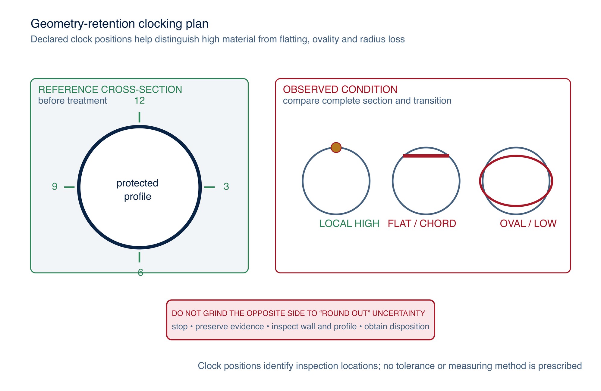
Geometry retention is a removal-control problem. The highest visual point may be weld reinforcement, a local bulge, a lighting highlight or the edge of an existing flat. Grinding it without a datum can enlarge the error.
Establish references outside the treatment zone and inspect more than one clock position. For a round section, use the approved combination of diameter measurement, radius or profile template, circumferential comparator, runout method, straightness check or scanned/CAD comparison. For a formed handrail or decorative tube, the controlled sample may add visual transition requirements, but it cannot replace wall or weld inspection.
A peer-reviewed study of belt grinding on shaped surgical-instrument surfaces assessed surface structure and roughness together with geometric accuracy and cross-section shape error. Its robotic system and numeric parameters are not transferable to hand-held tube finishing, but the quality principle is relevant: surface appearance and retained shape must be evaluated together. [S087]
Stop when the developing surface shows:
- a straight chord or flat reflection on a round section;
- a sudden change in radius at the blend boundary;
- an asymmetric profile across a weld;
- local diameter reduction or wall uncertainty;
- edge thinning at a tube end, slot, hole or junction;
- a bend that no longer matches the approved template; or
- a condition that changes after the work is released from its fixture.
Do not “round out” an uncertain section by grinding the opposite side. Protect the evidence and obtain engineering or quality disposition.
Select the contact system
The belt, contact element and machine form one system. Belt grain and grade do not determine conformity by themselves. Backing weight and flex, joint construction, width, edge condition, tension and tracking interact with the contact wheel, platen or slack section. [S050; S059]
| Contact mode | Appropriate screening question | Principal geometry risk |
|---|---|---|
| Narrow contact wheel | Can the footprint stay on authorised high material while the wheel follows the local radius? | Flat spots, grooves, edge lines or heat concentration |
| Wider compliant contact wheel | Does compliance support the specified curve without printing wheel shape or crossing protected zones? | Excessive blend width, radius loss or concealed local low |
| Slack belt or pipe-wrap system | Is the belt designed, tracked and guarded for the declared wrap and component size? | Wide uncontrolled removal, joint impact, belt-edge cutting or work pull |
| Platen-backed belt | Is the task truly a controlled flat or straight tangent feature? | A platen can impose a flat on a curved component |
| Non-woven or finishing belt | Is the task scratch refinement or visual blending rather than structural weld removal? | Slow cutting can encourage dwell, heat and over-processing |
Contact-wheel hardness, face pattern, diameter and compliance affect the footprint and response, but no universal ranking is issued here. Obtain the machine and belt manufacturer's declared combination and validate it on representative geometry.
Set up and monitor a tube belt
Before use, record the exact machine, belt designation, dimensions, direction mark, joint, maximum speed, material suitability and intended contact element. Inspect the belt edges and joint for cuts, creases, lifting, contamination, moisture damage or impact. Do not repair a failed production belt.
Set tracking and tension by the machine manufacturer's instructions before contact. Run the machine in a protected no-load condition when required and confirm that the belt remains centred without hunting, edge rub or joint strike. Recheck after belt change, contact-wheel change, tracking adjustment or abnormal vibration.
During grinding, keep the component stable and the belt path visible. A tube belt must not be allowed to climb over a fitting, catch a tube end, run onto a clamp or contact an unprotected adjacent finish. Stop if the belt moves sideways, the joint becomes audible or felt, the machine reaction changes or one belt edge produces a persistent line.
Storage and humidity can affect belt shape, backing and bond. Unsuitable conditions can contribute to curl, bowing, creasing, loading and grain-retention problems. Apply the exact product's storage instructions rather than a generic interval or humidity limit. [S051]
Control scratch direction
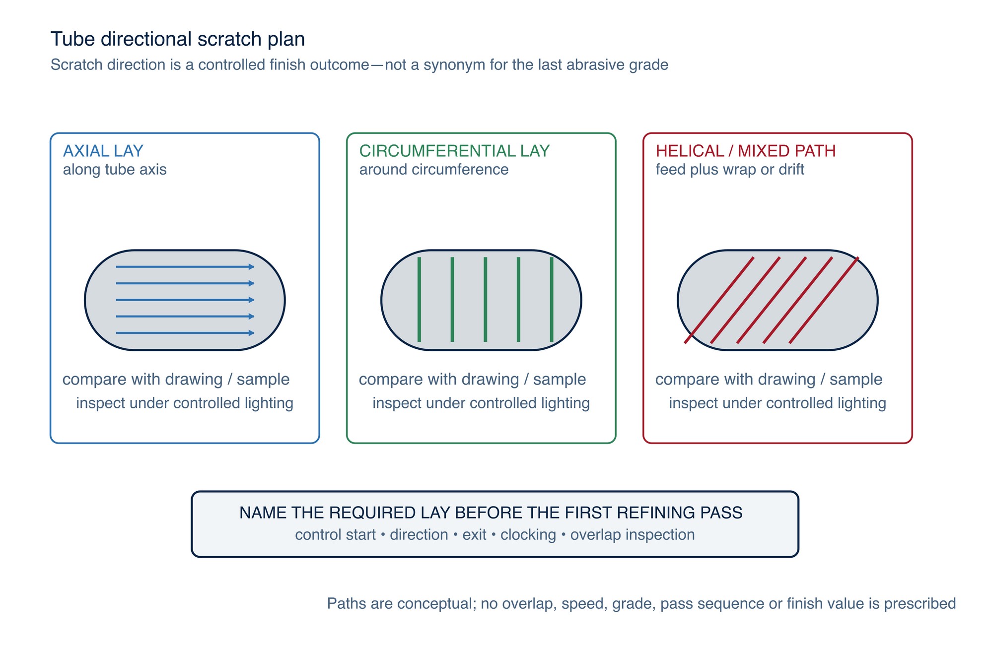
Every abrasive contact leaves a lay, even when the final surface appears visually non-directional. On tube, the principal paths are axial along the tube, circumferential around it, and helical when axial feed and rotation occur together. The required direction must be named before the first refining pass.
Circumferential scratches can form visible rings or bands when the belt dwells at one station. Axial scratches can wander, fan or cross at a bend. A helical trace can appear when the tool advances while the work or belt wraps around the circumference. These patterns are not automatically defects; they become defects when they conflict with the drawing, approved sample, functional requirement or adjacent surface.
BSSA describes ground and brushed stainless finishes as directional and warns that grit alone does not define the result. Therefore match the approved lay, texture and viewing condition rather than merely repeating the last belt grade. [S028]
Plan the pass and clocking sequence
Divide the component into identifiable zones using the approved drawing or fixture references. A controlled pass has a declared start, direction, exit and inspection gate. Avoid stopping at the same clock position on every pass, and avoid short repeated strokes that produce a ring, hollow or local heat band.
For local weld blending, remove only the authorised high material before expanding the transition. Re-establish the profile after each controlled interval. For full-circumference finishing, use an approved sequence that covers the complete circumference without leaving an untreated stripe or repeatedly overworking an overlap band. No universal clocking order, overlap or number of revolutions is prescribed.
At a bend, keep the belt orientation aligned with the local surface normal and the specified lay. The inside and outside radii do not present the same contact condition. Stop and reconfigure rather than twisting the belt or forcing the machine through a changing radius.
Blend welds, bends and handrail junctions
Handrails combine cosmetic visibility with functional geometry. Straight tube, elbows, mitres, posts, returns and branch junctions can require different access and scratch paths within one assembly. Establish a zone plan before grinding so that one corrected weld does not create a broad mismatched halo.
Confirm that the specified as-welded visual or NDT inspection has been completed before grinding. ISO 17637 provides a framework for visual testing of fusion-welded joints, while the component drawing, weld quality level and repair procedure remain controlling. [S078]
For a handrail junction:
- document the starting weld and surrounding finish;
- identify the weld reinforcement permitted for removal and the protected parent-metal profile;
- select the smallest controllable system that can access the joint without striking the adjacent tube;
- blend the weld in short controlled stages while checking both intersecting profiles;
- refine scratches into the specified direction on each member;
- match the agreed sample under controlled lighting; and
- inspect weld, wall, junction radius, adjacent finish and cleanability before release.
Do not erase a junction line, sharpen a comfortable handrail transition, thin the toe region or create a local flat merely to make the reflection look continuous.
Manage heat, loading and contamination
Curved contact can hide the active interface. Heat may concentrate under the wrap while the visible belt appears to be moving normally. Stop for rising local heat, discolouration, smearing, reduced cutting, loading, glazing, belt-edge marking or an altered machine reaction. Clean and inspect by the approved method; do not add force to restore cutting.
For stainless steel, segregate abrasive products and cleaning tools from carbon-steel use. BSSA identifies contaminated finishing media as a source of rust staining on mechanically finished stainless surfaces. [S028]
Do not introduce water, compound, solvent or another lubricant unless the complete belt, machine, electrical system, material, contamination plan and workplace procedure are declared for it. Manufacturer product examples cannot be converted into a universal wet-use instruction.
Inspect the curved surface
Inspect before, during and after grinding. Use lighting that reveals both the lay and the profile. Rotate or view the component from controlled clock positions instead of accepting one favourable reflection.
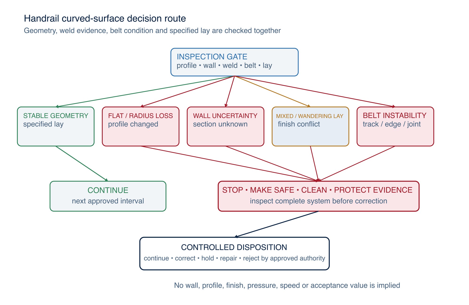
At each inspection gate:
- stop and make the machine safe;
- clean the work by the approved method;
- inspect belt, joint, edges, tracking, contact element and workholding;
- re-establish the datum and clock references;
- compare the treated zone with the required profile or template;
- inspect diameter, wall, radius, straightness, roundness or transition as specified;
- inspect scratch direction, depth, overlap bands and adjacent finish;
- verify weld and indication disposition; and
- record continue, correct, hold, repair or reject.
Do not measure against a hot, contaminated or elastically restrained condition unless the inspection plan expressly defines it.
Troubleshooting curved-surface defects
| Signal | Likely system cause | Controlled response |
|---|---|---|
| Flat reflection or chord develops | Narrow repeated path, excessive local removal, rigid contact or poor clocking | Stop; compare the full cross-section with the approved profile and obtain disposition |
| Circumferential rings or bands | Dwell, repeated start/stop position, uneven overlap or loaded belt | Stop; inspect profile before any wider blending; correct the process cause |
| Helical scratch where axial lay is required | Simultaneous wrap and feed, drifting tool angle or moving work | Stop; identify the actual path and revalidate the finishing method |
| One belt edge cuts a line | Tracking drift, tilted machine, damaged edge, joint or contact-wheel misalignment | Stop machine; quarantine uncertain belt and inspect the complete belt path |
| Weld disappears but a low remains | Excess removal, starting underfill, deflection or wrong datum | Hold for weld, wall and profile inspection; do not widen the low |
| Bend shows different gloss or scratch density | Changing contact footprint, pressure, belt speed response or viewing angle | Recheck contact mode and approved sample under controlled lighting |
| Work rotates, pulls or vibrates | Inadequate restraint, belt snag, unstable wrap, unbalanced contact or poor access | Stop immediately; make safe and redesign support or access |
| Rust staining or dark transfer appears | Mixed-metal contamination, dirty support or contaminated finishing media | Segregate, preserve evidence and follow the approved stainless-cleaning disposition |
Controlled curved-surface workflow
- Identify component, material, wall, diameter or profile, bend and traceability.
- Confirm authorised removal, weld disposition, protected geometry and final lay.
- Record starting profile and finish at declared clock positions.
- Select the exact machine, belt, contact element, guard and workholding system.
- Verify belt size, direction, joint, condition, speed compatibility, tension and tracking.
- Protect ends, holes, fittings, adjacent tubes, finished zones and datums.
- Validate contact mode, wrap response, footprint, pass direction and inspection gates on representative work.
- Remove only authorised high material while preserving the profile reference.
- Stop, clean, inspect and re-reference at each approved interval.
- Refine scratches into the specified lay without overworking one clock position or overlap band.
- Hold for flatting, ovality, wall uncertainty, mixed lay, heat, instability or unexpected indications.
- Complete geometry, weld, texture, cleanliness and visual inspection; record disposition and release.
Applying curved-surface grinding guidance
Match the contact system to the diameter, radius, wall thickness, weld location and finish direction. Keep wrap and contact controlled: excessive wrap or dwell concentrates heat and can create flats, while insufficient contact can create narrow bands or unstable tracking. Index or clock the work systematically so adjacent passes overlap consistently around the circumference.
Inspect roundness, wall, radius, straightness and transition shape as required, together with scratch direction, banding, heat and contamination. Blend bends and handrail junctions with a planned direction that connects the adjacent surfaces. Follow the current machine instructions. Refer to the product label, Technical Data Sheet, or MKTECH representative.
Curved-surface grinding record
For repeatability, record the component and traceability; material, wall, nominal diameter or profile and bend radius; drawing, weld, grinding and inspection revisions; starting weld, geometry and finish; authorised removal; protected zones, datums and clock positions; workholding; machine, guard and guide system; exact belt, joint, direction, batch and condition; contact wheel or slack-belt configuration; speed compatibility; tracking and tension checks; contact and wrap mode; pass and clocking sequence; inspection gates; heat, loading and belt observations; geometry results; scratch direction and finish comparison; weld indication result; contamination check; and repair disposition.
Cutting-Wheel Construction and Selection
The next chapter, Cutting-Wheel Construction and Selection, appears on the following page of the printed handbook (page 135), outside this chapter extract.