
Production engineers, supervisors, cutting and grinding operators, fabricators, maintenance teams, safety personnel, QA/QC personnel, trainers and technical sales personnel
Straight cutting with a hand-held angle grinder and an identified bonded cutting-off wheel: machine alignment, entry, maintaining the cut line, avoiding twist and side load, work support, pinch prevention, spark direction, interruption and safe completion. Exact product selection, machine settings, travel direction, numerical feed or force, support dimensions and acceptance values come from the identified machine and wheel instructions and the task requirements.
Use this chapter only after the complete wheel–machine–material system has passed Chapter 018. Follow the current wheel and machine instructions, task risk controls and local hot-work requirements. Use the correct guard, both hands and stable footing; keep people outside the line of fire; secure and support the work so it cannot move or pinch the wheel; maintain one cutting plane; and never steer, deepen or recover a cut by twisting, swinging or side loading a cutting-only wheel. If the wheel binds, walks, chips, vibrates, slows abnormally or control is lost, release the switch and hold the tool motionless until the wheel stops. Isolate and inspect before any re-entry. [S032; S090–S092; S095; S097]
Chapter objectives
After this chapter, the reader should be able to:
- define a straight cut as a controlled alignment problem;
- align the machine, guard, wheel plane and marked cut line;
- plan first contact without treating entry angle as a universal number;
- maintain the cut line without twist, swing or side load;
- support the stock and off-cut while preventing kerf closure;
- place the operator and others outside credible kickback and debris paths;
- control spark direction and hot material;
- interrupt, inspect and restart a cut safely;
- complete the cut without losing control of the wheel or off-cut; and
- create a traceable cutting-technique qualification record.
Correct technique is a controlled relationship
A straight cut is not produced by one hand angle or by pushing harder. It is produced when the intended kerf, wheel plane, machine, guard, operator, work support and material response remain compatible from first contact through separation.
The technique must control six relationships:
- wheel to machine: the selected wheel, guard, spindle, flanges and speed remain compatible;
- wheel plane to cut line: the wheel edge follows one intended plane without lateral steering;
- machine to operator: both hands, handle positions, footing and view permit stable control;
- work to support: the stock and off-cut cannot move, sag, rotate or close the kerf;
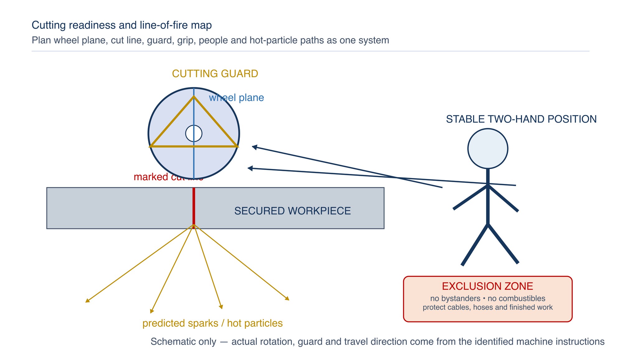
- rotation to line of fire: body, bystanders, cables, hoses and combustibles remain outside credible fragment, kickback and spark paths; and
- cut to acceptance: kerf, edge, burr, heat and remaining allowance are inspected under the approved plan.
ISO 11148-7:2012 covers safety requirements for operator-supported non-electric grinders used for cutting-off. HSE, FEPA and CCOHS provide regulator and industry best-practice controls, while current manufacturer manuals define the exact controls for their machine families. This chapter combines those compatible principles into an actionable baseline without inventing machine-specific numbers. [S090–S091; S096–S098]
Establish the cut plan before starting
Confirm the cut requirement before the wheel rotates:
- exact material, grade, coating, contamination restriction and cross-section;
- drawing, cut line, allowance, datum and required downstream edge condition;
- exact machine, wheel, guard, handles, flanges and maximum-speed compatibility;
- access for the complete cut without guard removal or an unstable body position;
- stock support, off-cut control and predicted kerf-opening or kerf-closing movement;
- hidden services, pressure, stored energy, residual stress and structural consequence;
- spark, fragment, dust, noise, fire and hot-material controls;
- bystander exclusion and the operator’s escape path;
- inspection method for line, kerf, edge, burr, heat and wheel condition; and
- the authority to stop, hold, rework or reject.
Do not begin a blind or structural cut until the work has been identified and made safe. A wheel entering an unknown wall, vessel, assembly or enclosed section can contact electrical conductors, pipes, pressure, combustible residue or restrained material. Manufacturer warnings require extra caution in blind areas because the wheel can encounter hidden services and kick back. [S097]
Align the machine and operator
Machine alignment begins before entry. Hold the machine firmly with both hands using its intended gripping surfaces and auxiliary handle. Establish stable footing and a body position that can resist start-up torque and a credible kickback reaction. Do not stand in line with and directly behind the rotating wheel or place a hand near the wheel plane. [S097]
Set the guard required for cutting and position it as the exact manual directs. The guard must not be removed or opened to obtain a view or reach. Plan a line of sight that does not place the face or torso in the fragment path.
Align three visual references:
- the marked or fixtured cut line;
- the plane of the wheel; and
- the direction in which the machine can travel without wrist rotation, body overreach or guard interference.
If the required path cannot be reached while maintaining both-hand control, guard coverage and stable footing, change the work arrangement or machine. Do not compensate by one-handed cutting, reaching around the wheel, rotating the guard away or fitting an unapproved wheel.
Support the stock and control the off-cut
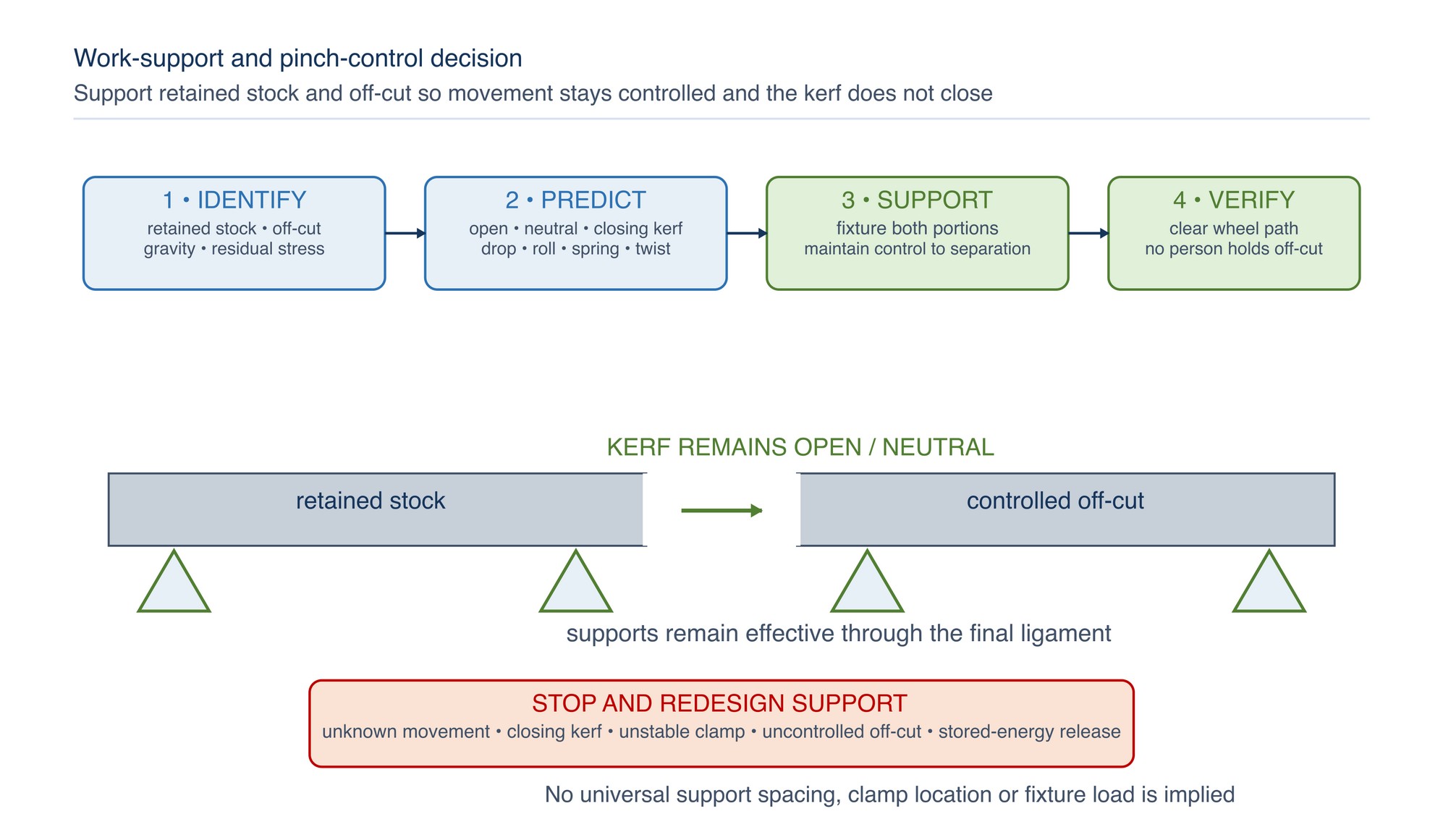
The work must remain stable under gravity, cutting force and final separation. “Clamped” is not enough if the arrangement closes the kerf, lets the off-cut rotate, or releases stored stress into the wheel.
Assess:
- which portion is retained stock and which is the off-cut;
- whether either side can sag, roll, spring, twist or drop;
- whether the kerf tends to open, remain neutral or close as the cut deepens;
- whether a clamp or support can become loose after separation;
- whether residual forming, welding, straightening or assembly stress may be released;
- whether the off-cut can strike the operator, wheel, cable, floor or nearby equipment; and
- whether support can remain effective through the last ligament of material.
Large panels and other flexible work require support near the cut and edges to reduce pinching risk, but exact support positions depend on geometry, stiffness, restraint and the intended separation. A person must not substitute for a fixture by holding the off-cut. Unknown movement, stored stress or support behaviour is a hold condition. [S090; S097]
Enter the cut under control
Entry angle describes the relationship between the wheel plane, its working edge and the work at first contact. It is not a universal degree value.
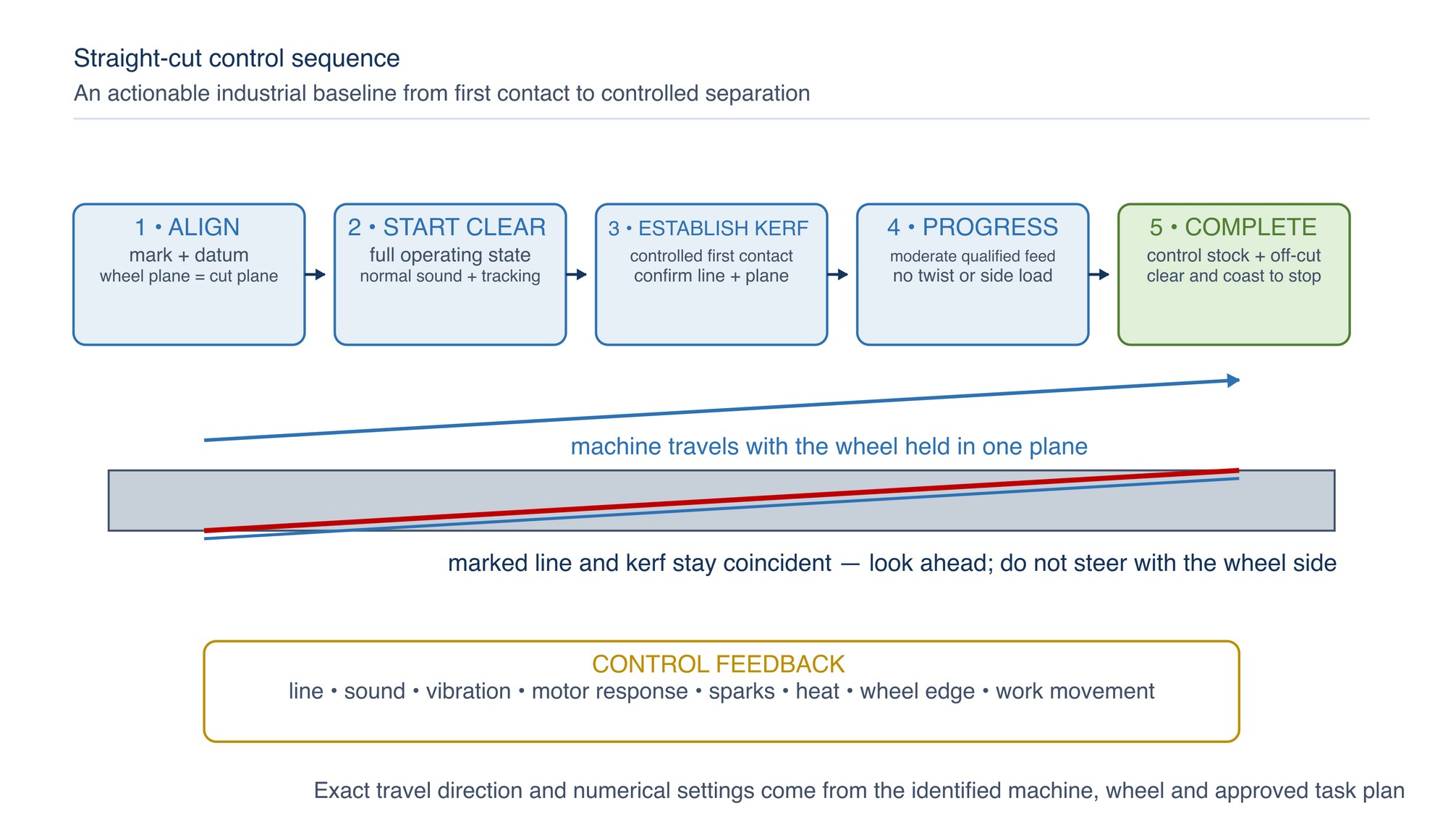
Before contact:
- verify the wheel and work are clear of people, loose items and services;
- start in the position and direction required by the exact machine manual;
- allow the wheel to reach the operating state required by that manual;
- confirm normal sound, vibration, guard position and wheel tracking; and
- approach the marked line without bumping the work.
Establish a shallow, controlled kerf that confirms the line and plane before committing to depth. The wheel plane must agree with the intended cut plane at entry. Do not start with the wheel trapped in the work, stab the edge into the material, or use side pressure to make the wheel “find” the line.
Machine instructions may prescribe moderate feed, prohibit pressure, tilt or swing, and require a particular travel direction. Follow the exact machine and abrasive instructions rather than generalising travel direction or feed technique across grinders. [S097]
Maintain one cutting plane
Once the kerf is established, progress along the planned line while keeping the wheel in the same plane. The operator guides the machine; the cutting edge removes material. Added force is not a substitute for wheel suitability, machine power, support or a straight path.
Use the following control logic:
- maintain both-hand control and a neutral, stable stance;
- look ahead along the cut line rather than watching only the contact point;
- use a qualified, moderate feed that keeps the cutting action stable;
- keep the wheel plane aligned with the kerf as depth and wheel diameter change;
- let the guard and handles remain in their approved positions;
- prevent the cable, hose or extraction equipment from entering the wheel or off-cut path;
- monitor sound, vibration, motor response, sparks, heat, wheel edge and work movement; and
- pause for inspection before drift becomes a forced correction.
Never twist the machine to steer a rotating cutting-only wheel. Do not swing the rear of the machine, lean the wheel against a kerf wall, widen the cut by side motion or use the wheel side to remove a high spot. These actions add lateral load, can cause binding and can fracture the wheel. [S090–S092; S097]
If the line is lost, do not bend the wheel back toward it. Interrupt the cut, wait for full stop and inspect whether the existing kerf can be safely re-entered, whether a new controlled kerf is permitted, or whether the part must be held for disposition.
Prevent binding, walk-up and kickback
Kickback can follow a pinched or snagged wheel. The stalled contact can drive the machine opposite the wheel movement at the binding point, toward or away from the operator. A wheel may also break under the same conditions. [S097]
Binding risk rises when:
- the work closes the kerf or moves after support changes;
- the operator twists, swings or applies side pressure;
- the wheel is forced so deeply or heavily that the machine slows;
- the cut changes direction inside the material;
- a corner, sharp edge, weld, coating or section change catches the wheel;
- the off-cut drops, rolls or strikes the wheel;
- the wheel is damaged, unsuitable, worn or incorrectly mounted; or
- the cut is restarted with the wheel trapped in the work.
Do not solve slow progress by forcing the wheel. CCOHS states that the wheel must not be jammed, bent or pinched and cutting must not be forced until the motor slows. A slowing motor is a diagnostic signal: reduce demand, then verify wheel selection, machine response, support and material condition. [S090]
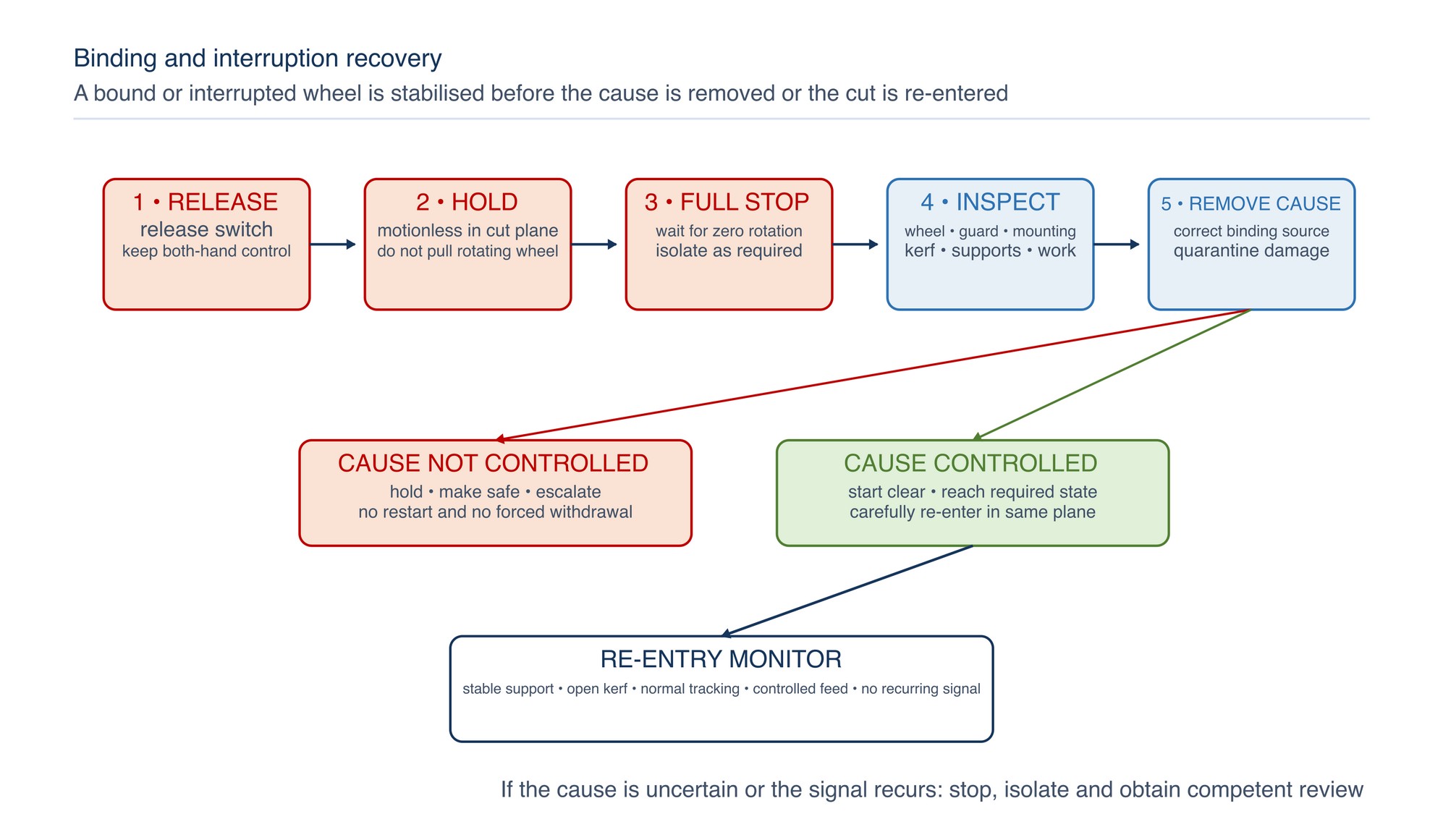
Interrupt and re-enter safely
If the wheel binds or the cut must be interrupted:
- release the switch;
- hold the machine motionless in the cutting plane;
- wait until the wheel comes to a complete stop;
- do not pull a rotating wheel from the kerf;
- isolate the energy source as required;
- inspect the wheel, guard, flanges, machine, kerf, support, work and off-cut;
- identify and remove the cause of binding or instability;
- quarantine a damaged or doubtful wheel; and
- re-enter only if the exact instructions, work condition and approval permit it.
Do not restart with the wheel inside the work. Manufacturer guidance directs the operator to let the wheel reach the required speed and carefully re-enter, because an in-cut restart can bind, walk up or kick back. [S097]
Control sparks, debris and hot material
“Spark direction” is not a single compass direction. It is the predicted path created by wheel rotation, contact point, guard position, machine travel and changing cut geometry.
Before cutting, confirm that sparks and fragments are directed away from:
- the operator’s face, torso, clothing and escape path;
- bystanders and adjacent workstations;
- flammable or combustible materials and residues;
- gas cylinders, hoses, cables, batteries and electrical equipment;
- finished surfaces, glass, vehicles and contamination-sensitive equipment;
- open containers, drains, voids and concealed spaces; and
- the intended support, clamp or off-cut control.
Do not rely on the visible main spark stream alone; fragments can travel outside it. Apply the current workplace hot-work, fire-watch, ventilation, respiratory, eye, face, hearing and clothing controls. The cut edge, off-cut, wheel and machine parts may remain hot after the visible sparks stop. Do not touch or release them until the approved cooling and handling method permits it. [S032; S090; S095; S097]
For stainless work, keep the wheel, supports, clamps, cleaning tools and surrounding debris under the approved contamination-control plan. Spark direction must not carry carbon-steel debris onto protected stainless work.
Complete the cut without losing the system
The final ligament can change the system suddenly. The off-cut may drop, rotate or spring; the kerf may close; the remaining stock may shift; and the wheel may break through into a new path.
Before final separation:
- confirm that stock and off-cut remain controlled;
- confirm the wheel has clear travel after breakthrough;
- maintain the same cutting plane and both-hand control;
- anticipate any change in support or stored stress;
- keep the body outside the expected tool and off-cut paths; and
- avoid a last-second push, twist or side correction.
After separation, maintain control until the wheel is clear and comes to a complete stop as the exact manual directs. Never slow a coasting cutting wheel with side pressure and never set down a machine with the wheel rotating. Preserve the cut part and off-cut for inspection if any abnormal signal occurred. [S097]
Geometry-specific completion paths for sheet, plate, tube, profile, hollow section and solid bar belong to Chapter 020.
Stop signals and controlled response
| Signal | Credible mechanism | Required response |
|---|---|---|
| Wheel binds or machine kicks | Kerf closure, snag, twist, side load, support movement or section change | Release; hold motionless to full stop; isolate and inspect |
| Motor slows or cutting action collapses | Excessive demand, unsuitable wheel, loading, unstable work or machine limitation | Stop adding force; hold and verify the complete system |
| Cut line drifts or kerf tapers | Misalignment, wheel deflection, side steering, run-out or work movement | Interrupt; do not twist back to the line; inspect and obtain disposition |
| New vibration, sound or wheel-edge change | Damage, looseness, imbalance, incorrect fit, chipping or contact instability | Stop immediately; quarantine the wheel and inspect the machine |
| Sparks or debris enter an unsafe zone | Guard, travel, body or work orientation is wrong or has changed | Stop; re-plan the line of fire and hot-work controls |
| Work or off-cut moves | Clamp/support change, sag, rotation, stored stress or final-ligament release | Stop; make safe; redesign support before continuing |
| Heat, discolouration, smear or coating damage | Rubbing, loading, slow progress, excessive contact or material response | Hold the part and process for technical and quality review |
| Guard, handle or view becomes obstructed | Access or arrangement no longer supports controlled cutting | Stop; change the arrangement or machine—do not remove controls |
Qualify the technique on representative work
A controlled trial must use the exact wheel, machine, guard, handles, flanges, work support and material form intended for production. Record the operator qualification and hold constant every input that is not being studied.
Evaluate:
- ability to establish and maintain the intended cut plane;
- stable machine response without forcing, twist or side load;
- stock, kerf and off-cut behaviour through final separation;
- spark, debris, dust, noise, vibration and hot-work control;
- interruption and safe re-entry where the plan requires it;
- cut time and accepted output without turning time into a speed target;
- kerf, line position, straightness, squareness and remaining allowance;
- burr, edge breakout, heat, discolouration and coating condition;
- wheel wear, edge condition and any damage; and
- downstream deburring, welding, cleaning, machining or rework.
Approve one exact revision of machine, wheel, material, support, cut path, operator method and inspection plan. Any material change returns the technique to controlled review. [S036; S097]
Applying correct cutting technique
Begin with a complete compatibility check: identified wheel, suitable machine, correct guard and flanges, secure work support and a clear cut line. Position the operator outside the likely line of kickback and debris, enter without impact, maintain one cutting plane and let the wheel cut without twisting or forcing.
Plan how the kerf and off-cut will move before starting. For interrupted cuts, release the switch and wait for a complete stop before inspecting or repositioning. Confirm cut line, squareness, burr, heat and wheel condition after the cut. Follow the current machine instructions. Refer to the product label, Technical Data Sheet, or MKTECH representative.
Cutting-technique record
For repeatability, record the task, component, material and grade, coating, cross-section, drawing, datum, cut line, allowance, downstream process, acceptance method, machine and asset, machine manual revision, wheel manufacturer/family/code/batch, wheel type and dimensions, guard, handles, spindle, flanges, maximum-speed check, work support, clamps, off-cut control, predicted kerf movement, stored-energy check, operator position, line of fire, spark/fire controls, PPE and exposure controls, entry method, machine-prescribed travel direction, feed or depth control, interruption and completion methods, cut time, kerf, line, squareness, burr, edge, heat, wheel condition, abnormalities and rework.
Cutting Sheet, Tube, Profile and Solid Bar
This next-chapter title appears on the final page of this chapter extract (page 151) of the printed handbook; the full Chapter 020 content follows outside this extract.