
Production engineers, supervisors, cutting and grinding operators, fabricators, maintenance teams, safety personnel, QA/QC personnel, trainers and technical sales personnel
Geometry-specific planning and execution for abrasive cutting-off with a hand-held angle grinder and an identified bonded cutting wheel. It covers thin sheet, thick plate, round tube, square tube, angle iron, channel, hollow section, solid bar, stainless pipe and aluminium profile. Chapters 018 and 019 remain mandatory for wheel–machine selection and correct cutting technique. Finished-cut defect diagnosis belongs to Chapter 021.
Do not cut live, pressurised, contaminated, unidentified or inadequately isolated pipe, equipment or structural work. Establish the material, contents, stored energy, residual stress, support, off-cut movement and hot-work controls before selecting a cut path. Secure both retained stock and off-cut. Maintain the cutting wheel in one plane. When a hollow or open section must be indexed, release the switch, hold the tool until the wheel stops completely, place the tool safely, then reorient and re-clamp the work before aligning the next segment. Never roll or rotate a workpiece while a hand-held cutting wheel is engaged. Use a safer machine or cold-cutting method when guarded reach, support, spark control or geometry cannot be maintained. [S090; S097; S099–S102]
Chapter objectives
After this chapter, the reader should be able to:
- classify work as flat, hollow, open-profile or solid geometry;
- transfer one cut plane across faces or around a circumference;
- support retained stock and off-cut so the kerf stays open or neutral;
- select a controlled wall-by-wall or face-by-face sequence;
- apply separate methods to the ten specified material forms;
- identify pipe-isolation and locked-in-stress hold points;
- control the final ligament and breakthrough path;
- choose a safer alternative when the wheel cannot reach while guarded;
- inspect the completed cut without assuming it is ready for downstream work; and
- qualify and record one exact geometry-specific cutting system.
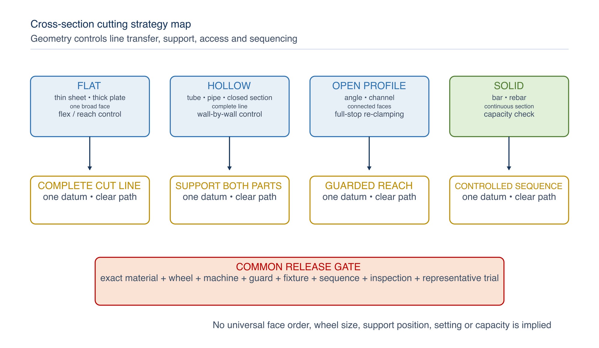
Geometry changes the cutting system
Material chemistry tells the selector which product declaration is required. Geometry tells the planner how the work can move, how the wheel enters, how many walls or faces must be crossed, and what happens at final separation. These are separate decisions.
Use four geometry families:
- flat work: thin sheet and thick plate expose one broad face but differ greatly in stiffness, heat response and required reach;
- hollow work: round tube, pipe, square tube and hollow section contain multiple walls and a void, so the cut line must be transferred and each wall controlled;
- open profiles: angle and channel combine legs, flanges, webs and corners that change contact and stiffness; and
- solid sections: solid bar maintains continuous engagement and can exceed the safe guarded reach or practical capacity of a hand-held wheel.
The identified wheel must be declared for the material and application. Cutting-wheel ranges commonly distinguish steel, stainless steel and aluminium, and may further separate sheet, profiles and solid material. Read the exact declaration for each wheel; catalogue performance claims do not transfer to another product. [S093]
Common geometry-control method
Apply this sequence before the form-specific sections:
- identify material, grade, coating, cross-section, wall condition and downstream requirement;
- establish that the work is not live, pressurised, contaminated, energised or structurally loaded beyond the approved task boundary;
- select the exact compatible wheel–machine–guard system under Chapter 018;
- choose one datum and mark the complete cut plane on all accessible faces or around the full circumference;
- predict roll, sag, spring, twist, drop and kerf closure for both stock and off-cut;
- secure and support both portions through the final ligament, leaving a clear guarded wheel path;
- choose the accessible face or wall segments that can be cut while the wheel remains in one plane and both hands remain on the machine;
- define every stop, full-stop, reorientation, re-clamping and alignment point;
- plan final-ligament movement and a clear breakthrough path; and
- define inspection, hold, rework and acceptance authority before starting.
The line on a multi-face component must come from one datum. Independent marks made “by eye” on separate faces can produce offset kerfs and tempt the operator to twist the wheel to join them. If the line cannot be transferred accurately, use an approved template, wrap, square, fixture or machine.
Clamping is effective only when it prevents movement without distorting thin work or closing the kerf. HSS guidance requires work to be secured and supported on both sides of the cut; the exact support locations remain a task-design decision. [S102]
Thin sheet
Thin sheet is flexible, heat-sensitive and easily pulled into vibration. First decide whether abrasive cutting is appropriate. A shear, nibbler, guillotine or other assessed cold-cutting method may provide better fire, distortion, burr or coating control. CCOHS identifies substitution as a valid hot-work risk-reduction option, provided the alternative is also assessed. [S099]
For an approved abrasive cut:
- support the sheet flat on a clean, non-combustible arrangement that leaves wheel clearance below the line;
- clamp the retained sheet and control the off-cut so neither portion flutters, lifts, tears, drops or contacts the wheel;
- protect finished or coated surfaces from clamp damage, sparks and embedded debris;
- align the complete cut path before contact and confirm that the guard and handles remain clear;
- establish a controlled kerf, then progress along the same plane without deep plunging into an unsupported flexible span; and
- reduce demand and stop if the sheet vibrates, buckles, discolours, pulls into the wheel or loses support.
Do not hold thin sheet by hand, ask another person to hold it, or use body weight as a fixture. Do not bridge a long flexible span in a way that lets the kerf close. If support blocks wheel travel, redesign the arrangement; do not remove the guard or tilt the wheel around the obstruction.
At completion, keep both portions supported. A narrow strip or small off-cut can become hot, sharp and mobile. Allow it to separate without pushing the wheel sideways, then control it with the approved handling method after the wheel stops.
Thick plate
Thick plate has greater stiffness and thermal mass, but it increases engagement, cutting time and guarded-reach demand. Before using a hand-held grinder, verify that the wheel can complete the intended path within the usable capacity permitted by the current machine and wheel instructions. Nominal wheel diameter is not usable cutting depth.
Use this method:
- support retained plate and off-cut so the kerf will open or remain neutral as the cut deepens;
- provide an accessible straight path with stable footing and two-hand control for the entire length;
- establish one kerf and deepen or progress it in the same plane using qualified moderate feed;
- monitor motor response, vibration, heat, wheel condition and plate movement; and
- plan the last ligament before cutting demand or support behaviour changes.
Do not chase a wandering kerf by leaning on the wheel side. If the intended thickness cannot be reached while guarded, or the plan depends on blindly meeting cuts from opposite faces, stop and select a more suitable saw, cutting machine or qualified fixture. A second-face method may be used only when the line-transfer and re-clamping process has been specifically qualified for that plate and system.
Round tube
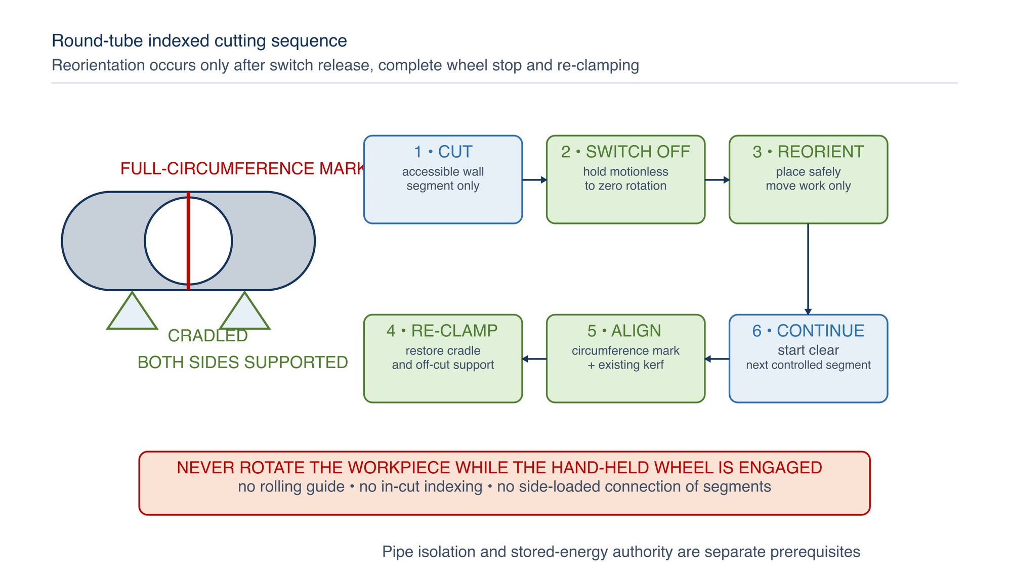
Round tube can roll, collapse under poor clamping and misalign at the join between indexed segments. Mark the cut around the full circumference with an approved wrap or squaring method. The line must return to its starting point without a step.
Use a cradle, pipe vice or qualified fixture that prevents rolling and excessive ovalisation. Support the retained tube and off-cut on both sides. Orient the first accessible wall segment so the wheel can enter in one plane with the guard, handles and body clear.
Cut only the accessible segment that can be controlled in that setup. If another segment requires reorientation:
- release the switch;
- hold the machine motionless until the wheel stops completely;
- place or isolate the tool as the procedure requires;
- reorient the tube without exposing a person to roll, spring or hot edges;
- re-clamp and re-check both supports;
- align the wheel to the continuous circumference mark and existing kerf; and
- start clear and continue under Chapter 019.
Never roll a tube against an engaged hand-held wheel and never use the kerf as a rotating guide. That motion can add side load, trap the wheel and place the operator in an uncontrolled reaction path.
Square tube and rectangular hollow section
Square and rectangular hollow sections have faces joined by radiused corners. Mark every face from one datum. Verify that the last line closes accurately around the section. If coatings, weld seams or internal features change the cut response, include them in the plan.
Choose the most stable orientation that gives a visible, guarded path. Cut an accessible wall segment while maintaining one wheel plane. Do not swing the rear of the grinder around a corner to continue onto a hidden face. Instead, stop completely, reorient and re-clamp the section, then align the next face to the transferred line and the existing kerf.
The exact first face is not universal. Fixture access, section proportions, machine travel direction, weld seam, coating, support and final-ligament plan can change the safest order. A “corner-first” practice is acceptable only where the exact instructions and a representative trial have qualified it; it is not a handbook default.
Control the final wall or corner so the off-cut cannot twist, drop or close onto the wheel. If the section begins to rack, ovalise or spring, stop and redesign the restraint.
Angle iron
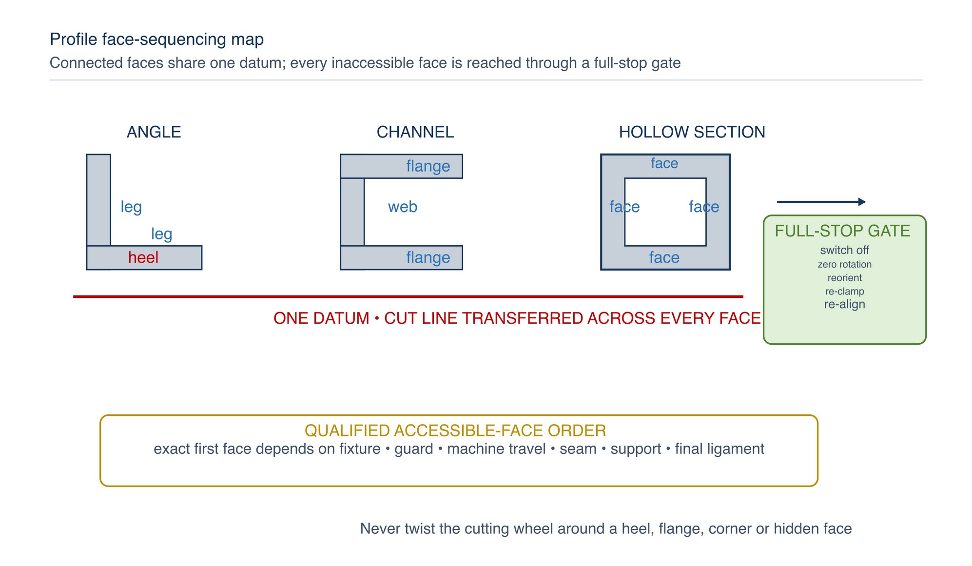
Angle iron comprises two legs and an included heel. Its open form can rock or spring when one leg is severed. Establish one square cut plane across both legs and the heel. Choose an orientation that supports the section without hiding the line or forcing the machine into the included corner.
Treat the profile as three connected features: accessible leg, heel transition and remaining leg. The exact order depends on fixture and machine access. Complete only the feature that can be cut in one plane; stop, reorient and re-clamp before the next feature when required.
Support the off-cut across both legs so the first cut does not turn the remaining leg into a hinge that closes the kerf. Do not twist the wheel through the heel to “turn the corner.” If the corner cannot be reached without side loading or guard interference, use a more suitable machine or qualified setup.
Channel
Channel contains two flanges and a web. The open side can make the profile unstable, while severing one flange can let the remaining section twist. Mark both flanges and the web from one datum.
Choose a stable supported orientation and identify an accessible flange, web and remaining flange sequence. Cut each accessible face in one plane. Stop completely and re-clamp before changing orientation. The exact flange-first or web-first order is not universal; it must agree with the fixture, current machine instructions, guarded reach and predicted movement.
Support the off-cut so a severed flange cannot drop against the wheel. The remaining web or flange must not carry uncontrolled bending load at final separation. Unexpected opening, closing or twisting indicates residual stress or inadequate support and requires a stop.
Hollow section
“Hollow section” includes square, rectangular and other closed structural profiles not already covered as simple tube. Begin by identifying walls, corners, seams, internal reinforcement, coatings, enclosed contamination and any structural load.
Use the square-tube principle: transfer one closed cut line, secure stock and off-cut, cut only accessible wall segments, and stop/re-clamp before reorientation. Complex hollow sections may require a purpose-built fixture, cold saw, band saw or other machine because a hand-held wheel cannot maintain guarded reach and alignment across every face.
Do not assume an enclosed section is empty or harmless. Openings can contain moisture, combustible residue, cable, insulation or pressure. Unknown contents or structural duty are hold conditions.
Solid bar
Solid bar keeps the wheel engaged across a continuous cross-section. It can roll, impose sustained demand and exceed guarded reach. Verify the exact wheel's declared application and the machine's usable capacity before choosing a hand-held method. The existence of products declared for rebar or solid material does not make every bar, machine or cutting wheel suitable. [S093; S101]
Cradle or fixture the bar against rolling and support the off-cut. Establish a square line and maintain one straight kerf. Do not rotate the bar while the wheel is engaged. If an indexed method is necessary, it must be qualified and must use the same switch-off, full-stop, reorientation and re-clamping gate as round tube.
If the wheel cannot reach through the cross-section while guarded, do not remove the guard, fit an oversized wheel or complete an uncontrolled rotating cut. Use a suitable chop saw, cold saw, band saw or other assessed cutting system.
Stainless pipe
Stainless pipe combines round-tube geometry, possible process contents and contamination-sensitive material. Before the abrasive method is considered, determine whether the item is unused stock, removed spool, installed service or formerly live pipework.
For process-connected or formerly live pipe, competent isolation authority must confirm that the cut cannot release fluid, create uncontrolled ignition or introduce another unsafe condition. HSE guidance calls for isolation, depressurisation, venting/draining and purging/flushing as appropriate, prevention of hazardous ingress, and support/restraint around the cut against pipe spring from locked-in stress. CCOHS likewise requires pressurised vessels, piping and equipment to be secured, isolated and vented for hot work. [S099–S100]
Only after those controls are proved may the round-tube sequence be applied. In addition:
- use a wheel whose exact current declaration covers the stainless grade/application;
- segregate the wheel, supports, clamps, marking and cleaning tools from carbon-steel contamination;
- keep carbon-steel sparks and debris away from the pipe and downstream clean area;
- control heat tint, burr and edge damage under the drawing and welding/cleaning plan; and
- treat the cut edge as unaccepted until inspected and prepared for its downstream duty.
An “INOX” or stainless declaration is a selection gate, not proof that the cut is weld-ready, corrosion-ready or contamination-free. [S009; S017; S028; S092–S093]
Aluminium profile
Aluminium profiles can be thin, hollow, open, coated and easily distorted. Aluminium can also load an unsuitable abrasive. Use only a product whose exact declaration covers the aluminium alloy, application and named machine. The availability of aluminium-specific wheels does not make an unidentified or general-purpose wheel suitable. [S093]
Apply the matching geometry method: flat support for sheet-like extrusion, face-by-face control for hollow profiles, or separate legs/webs for open profiles. Use clean protected supports that prevent collapse and surface damage. Remove or control combustible debris and assess the job as hot work.
Do not apply coolant or lubricant unless the exact wheel and machine instructions permit it. Loading, smearing, rising heat, unstable sparks, vibration, motor slowdown or edge tearing requires stop and inspection. Added force is not a remedy.
Where finish, heat, fire or distortion cannot be controlled, use an assessed aluminium-suitable saw or machining process.
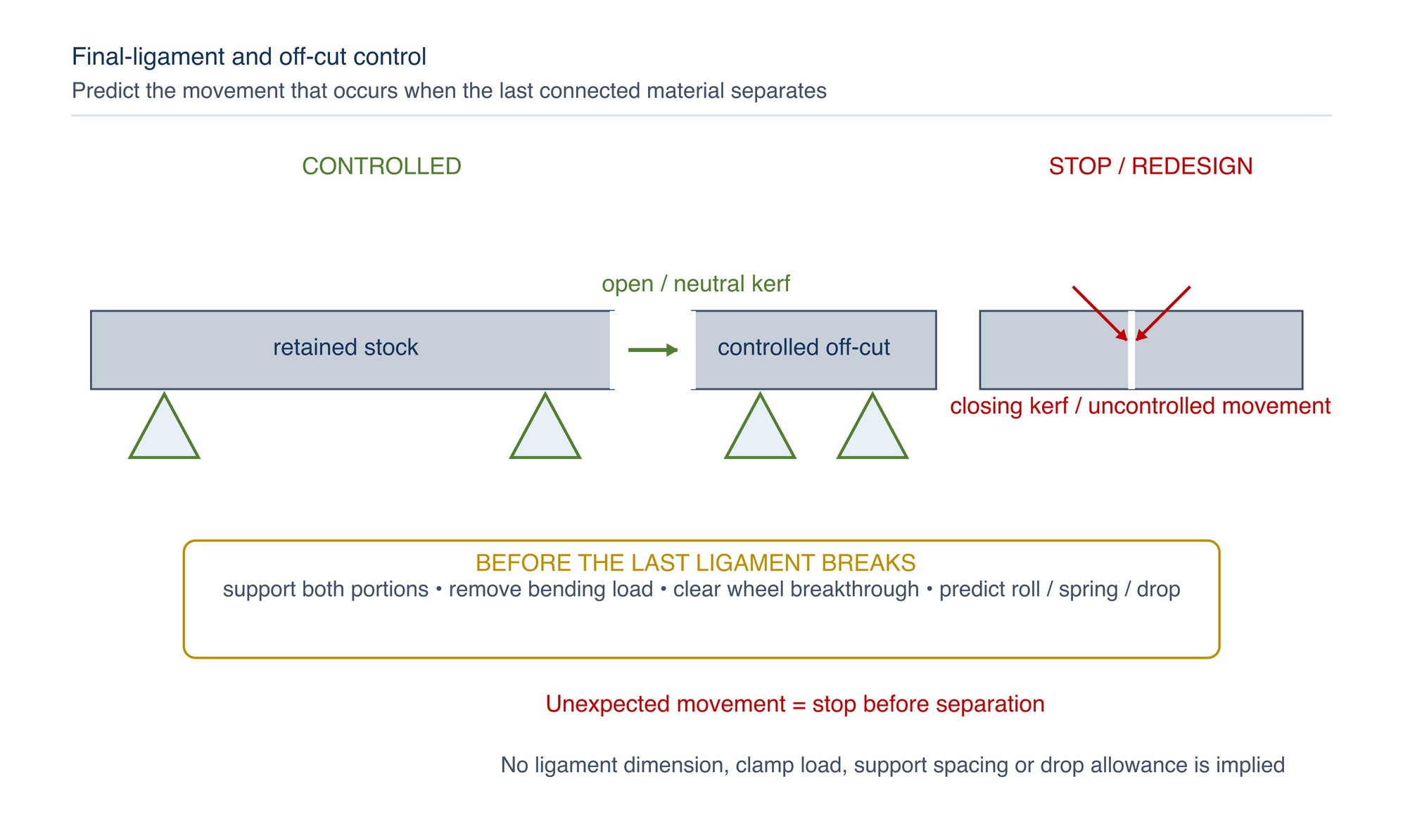
Final-ligament and breakthrough control
The final ligament is the last connected material before separation. Its location changes as walls and faces are cut. Before reaching it, verify:
- retained stock and off-cut remain supported in their expected final positions;
- the kerf will stay open or neutral rather than clamp the wheel;
- no remaining wall, flange or leg carries uncontrolled bending or torsional load;
- the off-cut cannot roll, swing, spring, drop or strike a person, wheel, cable or equipment;
- the wheel has a clear guarded breakthrough path; and
- both hands, body and escape path remain clear.
Do not accelerate separation with a final push or side twist. If movement differs from the prediction, stop before the ligament breaks and redesign the support.
Geometry selection and stop matrix
| Form | Primary movement risk | Support objective | Controlled sequence | Stop or change method when |
|---|---|---|---|---|
| Thin sheet | Flutter, buckling, tearing, hot mobile strip | Flat support near line; both portions controlled | Establish and progress one kerf without deep unsupported plunge | Sheet vibrates, pulls, discolours or loses support |
| Thick plate | Closing kerf, long engagement, inadequate reach | Keep kerf open/neutral and path accessible | One-plane progressive cut; qualified second-face method only | Guarded reach or straight access is inadequate |
| Round tube | Roll, ovalisation, segment mismatch | Cradle and support both sides | Wall segment; full stop; reorient/re-clamp; align | Tube rolls, line does not close, or final ligament is uncontrolled |
| Square/rectangular tube | Twist, corner catch, face mismatch | Stabilise section and final wall | Accessible face segments with full-stop re-clamping | Reaching a face requires wheel twist or guard interference |
| Angle | Rock, hinge action, heel binding | Support both legs and off-cut | Leg/heel/leg features in qualified accessible order | First feature loads or closes the remaining feature |
| Channel | Twist after flange separation | Support flanges, web and off-cut | Accessible flange/web/flange faces with re-clamping | Remaining face carries uncontrolled bending load |
| Hollow section | Hidden contents, multi-face mismatch | Prove contents; stabilise all walls | Transferred line and accessible wall segments | Contents, structure, reach or alignment is uncertain |
| Solid bar | Roll, sustained demand, incomplete reach | Cradle and support off-cut | Straight one-plane cut; qualified stopped index only | Wheel cannot pass while guarded or machine response deteriorates |
| Stainless pipe | Process release, spring, contamination | Prove isolation; restrain; segregate | Isolation gate, then round-tube sequence | Status, contents, gas-free condition, stress or cleanliness is unproved |
| Aluminium profile | Collapse, loading, smear, finish damage | Clean protected geometry-specific support | Matching face/flat sequence with aluminium-declared product | Loading, heat, vibration, tearing or finish damage appears |
Post-cut inspection and controlled disposition
After the wheel stops and the part is safe to handle, inspect against the drawing and task plan:
- line position, length and remaining allowance;
- squareness, angularity or end-face orientation using the approved datum;
- kerf join at indexed walls and faces;
- burr, breakout, tearing, local deformation and sharp edges;
- heat tint, coating damage, smear or embedded contamination;
- tube ovalisation, profile twist and section change;
- wheel edge, wear and any abnormal damage;
- retained stock and off-cut condition; and
- downstream deburring, machining, welding, cleaning or passivation requirements.
Do not force parts together, dress away evidence or automatically re-cut a stepped join. Protect the evidence and use the approved rework or disposition route. Detailed defect mechanisms and troubleshooting remain gated for Chapter 021.
Qualify the geometry-specific method
A representative trial must use the exact material form, chemistry, wall or section range, machine, guard, handles, wheel, flanges, supports, clamps and planned sequence intended for production. Record every stop/reorientation gate and the final-ligament arrangement.
Evaluate:
- line transfer around or across the complete section;
- secure support without distortion, roll or kerf closure;
- guarded access and two-hand control for every segment;
- stable machine response without forcing or side load;
- alignment between face or wall segments;
- stock and off-cut behaviour at final separation;
- hot-work, spark, debris, dust, noise and contamination controls;
- cut time as a recorded output, not a speed target;
- kerf, line, squareness, burr, heat, deformation and downstream allowance; and
- wheel condition, abnormalities, holds, rework and disposition.
For pipe, the trial record must reference the isolation and stored-energy authority. For stainless and aluminium, include segregation and material-specific inspection. Approve one revision of the complete system. A change in geometry, material, wheel, machine, guard, support, sequence, setting or acceptance method returns the process to controlled review. [S036; S093; S097; S100]
Applying the method to different sections
Select the cut path from the geometry, support and guarded reach. Sheet and plate require control of heat and line stability; tube and hollow sections require a transferred cut plane and controlled wall-by-wall sequence; angle and channel require attention to open faces and spring movement; solid bar creates a longer engagement; pipe requires verified isolation and stored-energy control.
Secure both the retained material and off-cut, keep the kerf neutral or opening, and complete each reachable segment in one plane. Stop the wheel fully before reorienting or re-clamping. Use stainless segregation where required and manage aluminium loading in accordance with the selected product. Follow the current machine instructions. Refer to the product label, Technical Data Sheet, or MKTECH representative.
Geometry-specific cutting record
For repeatability, record the task, drawing, material, grade, coating, form, dimensions, wall or section range, contents or service history, isolation or gas-free status where applicable, stored energy, residual stress, datum, line-transfer method, machine and asset, manual revision, wheel manufacturer/family/code/batch, declaration, dimensions, maximum-speed check, guard, handles, spindle, flanges, supports, clamps, cradle, off-cut control, predicted kerf movement, guarded reach, face or wall sequence, reorientation gates, entry and travel method, final ligament, hot-work controls, segregation controls, cut time, line, squareness, kerf joins, burr, heat, deformation, contamination, wheel condition, abnormalities and rework.
Cutting Defects and Corrective Action
The Cutting Defects and Corrective Action chapter begins on the following page of the printed handbook (page 161), outside this chapter extract.