
Production engineers, supervisors, operators, QA/QC personnel, maintenance teams, safety personnel, procurement staff and technical sales personnel
Practical control of grain direction, entry and exit, pass overlap, line straightness, tool speed, contact pressure, hand-held and machine finishing, repair blending and visual acceptance for industrial metalwork.
A directional finish is a controlled surface pattern, not simply a final grit. The accepted result depends on repeatable lay direction, scratch character, spacing, sheen, transitions and viewing conditions.
Use only abrasive products and accessories intended for the material, machine, mounting and finishing task. Confirm compatibility between the abrasive dimensions and speed rating, accessory, machine and guarding arrangement. Secure the workpiece and maintain stable support, stance and line of fire. Keep guards, handles, extraction, interlocks and other protective systems in place as required.
Chapter objectives
After this chapter, the reader should be able to:
- translate a finish requirement into a visible lay direction and repeatable datum;
- plan entry, exit, overlap and stroke sequence before contacting the workpiece;
- control line straightness without hooks, arcs, swirls or stop marks;
- understand how speed, pressure, contact support, abrasive wear and feed interact;
- select between hand-held, fixed-machine and automated finishing routes;
- blend a local repair without leaving a halo or abrupt boundary; and
- assess a directional finish against an approved reference under controlled viewing.
A directional finish is an engineered scratch pattern
Grinding, brushing and polishing create directional marks whose appearance depends on the complete finishing system. Abrasive construction, support, machine motion, contact shape, tool speed, travel speed, pressure, overlap, wear, material condition, cleanliness and lighting all influence the final pattern.
The words brushed, satin, dull polished and No. 4 do not define one universal appearance. British Stainless Steel Association guidance explains that a final grit alone does not fully define a mechanically finished stainless surface, while EN finish families distinguish ground, brushed or dull-polished, satin and bright-polished routes by broader surface characteristics. Agreed samples or clearly stated surface requirements remain essential where appearance matters. [S028; S119–S120]
For production control, describe the target through observable attributes:
- lay direction and datum;
- line straightness and continuity;
- scratch spacing, width and uniformity;
- sheen, reflectivity and colour;
- permitted transition or blend zone;
- edge, corner and feature condition;
- local-defect acceptance; and
- any separately specified roughness or functional requirement.
Establish the datum and controlled zone
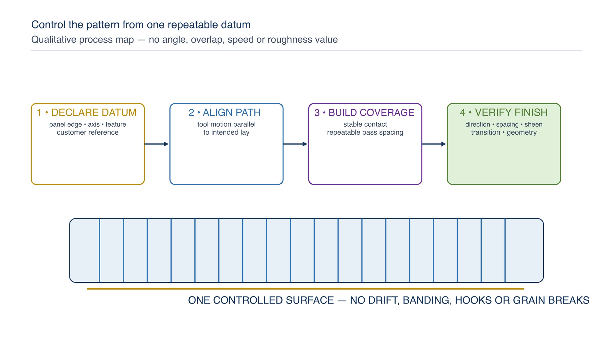
Define the lay from a part feature that different operators can recognise: longitudinal along a panel, transverse across a sheet, circumferential around a tube, axial along a shaft, radial from a centre or another drawing-controlled direction.
Before finishing, identify:
- the visible face and the controlled zone;
- the datum from which lay direction is judged;
- the start and exit zones;
- protected edges, holes, corners, weld toes and adjacent faces;
- the intended blend boundary;
- the accepted reference panel or production standard; and
- the lighting and viewing method for final assessment.
On assemblies, plan how the grain will continue across joints and adjacent panels. Two individually uniform panels can still look mismatched when their lay direction, sheen or line spacing changes at the joint.
Select the process by the required pattern
Choose the product form and machine motion that can produce the required lay on the actual geometry. Straight-line belts and wheels can support a linear grain; rotary discs naturally create arcs unless the process and subsequent steps remove them; hand pads can follow small or complex areas but depend strongly on operator control; fixed machines and automation can improve repeatability when their path, force and abrasive condition are controlled.
Stainless finishing commonly separates weld levelling, grain setting and final finishing. Straight-line tools can restore directional finishes, while rotary discs create a different motion signature. Match machine motion to the required surface pattern and do not transfer product-specific settings between systems. [S122; S128]
| Required outcome or geometry | Practical process direction | Control emphasis | Avoid |
|---|---|---|---|
| Long straight grain on flat sheet | Straight-line belt, wheel or guided linear hand process | Fixed datum, stable support, consistent path and wear state | Using a rotary arc as the final visible lay |
| Circumferential grain on tube | Tube-finishing belt or controlled wrap-around process | Even contact around the circumference and consistent axial position | Pausing at one quadrant or twisting the line |
| Axial grain on tube or profile | Linear belt, wheel or guided hand stroke along the axis | Support, straight entry and continuous exit | Helical drift or repeated short patches |
| Small repair in an existing finish | Compatible hand-held or small-machine route within a planned blend zone | Match the original direction, scratch character and sheen | Polishing only the defect into a bright island |
| Repeated production panels | Fixed-machine or automated route where practical | Controlled path, contact, feed, product condition and inspection | Assuming automation compensates for worn abrasives or variable parts |
| Complex formed feature | Conformable product with stable manual or programmed support | Protect edges and follow the declared local datum | Allowing the product to wrap uncontrolled over corners |
Control entry, contact and exit
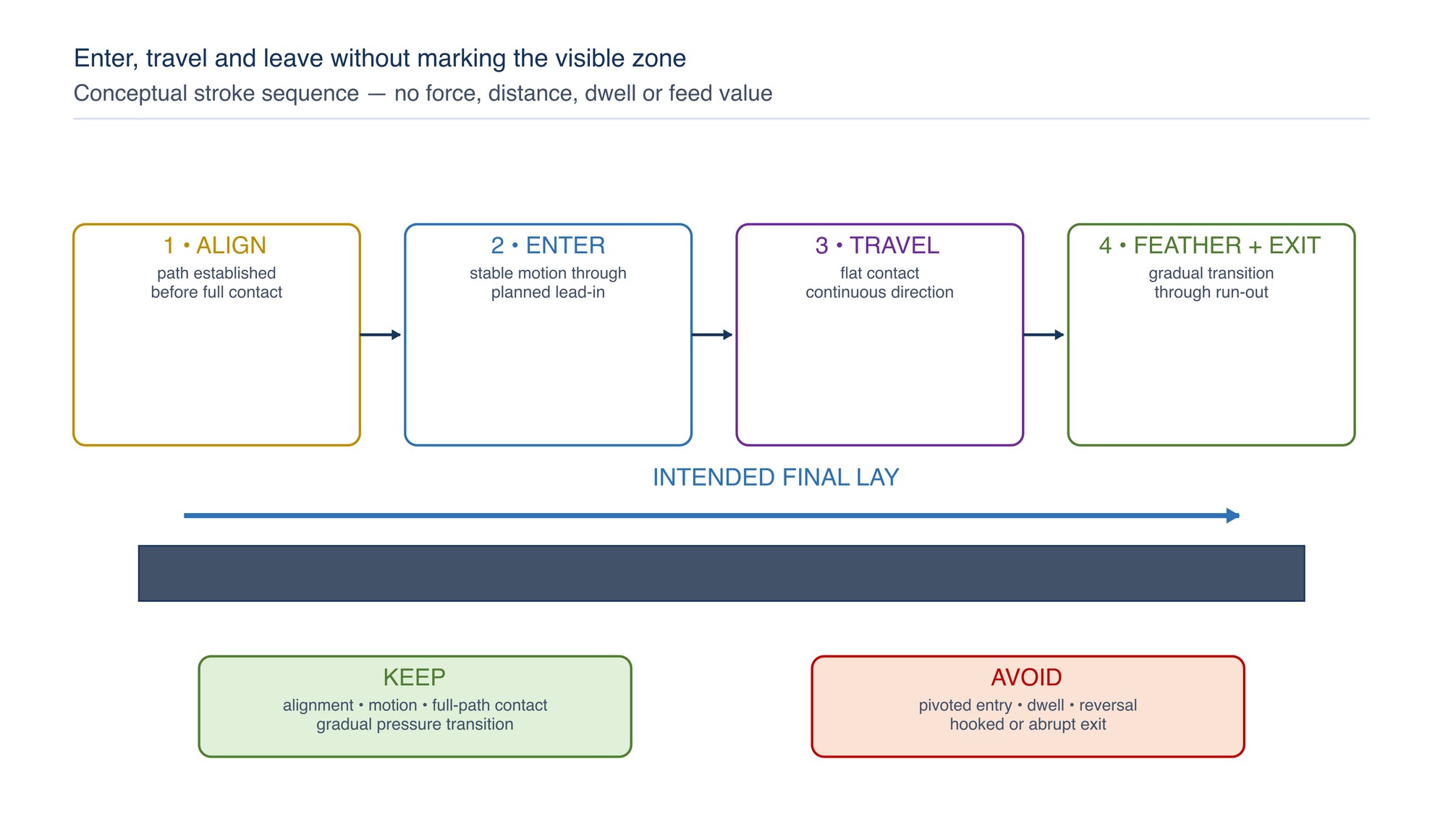
Start and stop marks occur when the abrasive contacts the visible zone without stable motion, dwells while cutting, pivots during a stroke or leaves the surface abruptly.
Use a deliberate sequence:
- align the tool, belt or workpiece with the intended lay;
- establish stable movement and support before full cutting contact where the equipment permits;
- enter through a planned lead-in or non-critical zone;
- maintain the intended contact footprint through the visible area;
- avoid stopping, reversing or pivoting while the abrasive is cutting;
- feather the pressure or contact gradually near the exit; and
- leave through a planned run-out zone without hooking the path.
Where the part has no sacrificial lead-in or run-out, reduce the visible effect by using controlled feathering, masking or a process specifically suited to the geometry. Do not create a dimensional step merely to hide a cosmetic mark.
Use overlap to build one continuous surface
Adjacent passes should read as one finish rather than separate stripes. Too little effective overlap can leave unworked bands or alternating sheen. Excessive repeated overlap can over-brighten a strip, change texture, generate heat or remove more material than intended.
Control overlap through visible reference points, guides, fixture position, programmed path spacing or other repeatable means appropriate to the job. The correct amount is not a universal percentage: it depends on the effective contact width, abrasive construction, wear state, support, geometry and required appearance.
Practical controls include:
- keep each pass parallel to the declared datum;
- maintain a consistent contact width and tool attitude;
- step across the surface in one planned sequence;
- avoid returning repeatedly to an isolated dull or bright stripe;
- inspect the whole panel under diffuse and low-angle light; and
- correct the process before adding more passes when banding persists.
Keep the grain straight and continuous
Line straightness is affected by the operator’s body position, tool balance, hose or cable drag, fixture alignment, workpiece movement, belt tracking, contact-wheel condition and the shape of the visible zone.
Use the longest practical reference for the job. A guide edge, fixture datum, machine axis, marked non-finish area or accepted reference panel can help operators recognise drift before it becomes a visible curve.
Watch for these pattern signatures:
- hook: the path curves at entry or exit;
- arc: a rotary tool leaves a visible circular segment;
- wander: successive lines drift away from the datum;
- cross-line: a corrective pass cuts across the intended final lay;
- banding: neighbouring passes have different sheen or scratch density;
- stop mark: a local bright, dark or coarse patch shows dwell; and
- grain break: direction or spacing changes at a weld, joint or panel boundary.
Balance speed, pressure, feed and contact support
Tool speed, travel speed, pressure and contact area work as a system. Changing one can alter cut rate, scratch depth, heat, sheen and abrasive wear. A faster tool is not automatically a finer finish, and additional pressure is not a reliable correction for loading, glazing, poor support or a worn product.
Use these qualitative controls:
- maintain the machine within the abrasive and accessory limits;
- use the product in the pressure range for which its construction is intended;
- keep travel smooth enough to avoid dwell and stable enough to maintain the lay;
- support the abrasive so the contact footprint matches the geometry;
- replace or condition products whose wear state changes the delivered finish;
- stop and investigate chatter, smearing, heat, bounce, streaking or tool stall; and
- confirm a setting change on a representative surface before applying it to the acceptance face.
Manufacturer troubleshooting guidance links heat, chatter, bounce, smearing and streaking to interacting speed, pressure, support and abrasive-condition variables. Exact corrective settings remain product-, machine- and material-specific. [S122]
Hand-held, fixed-machine and automated finishing
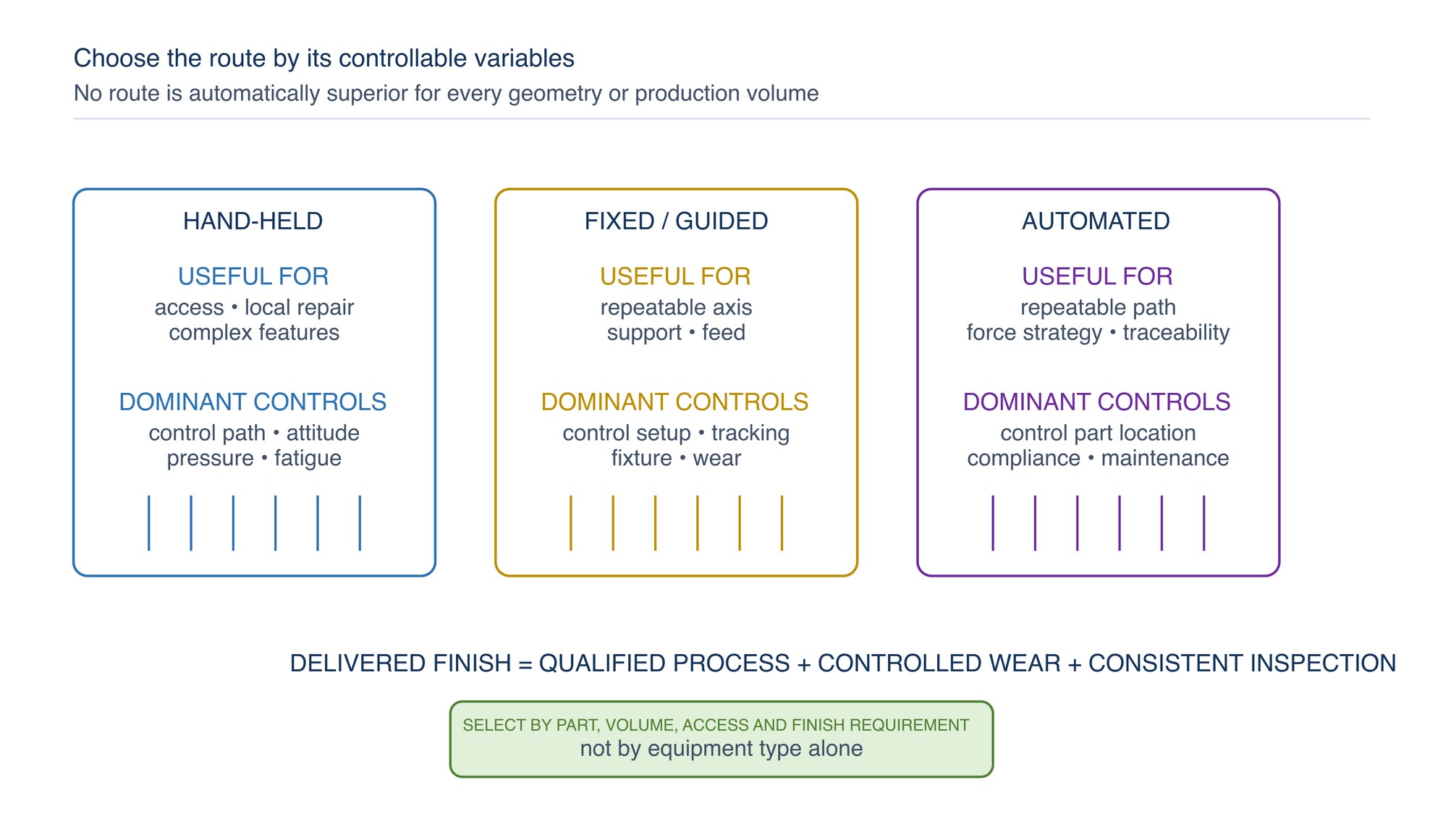
The best route depends on geometry, production volume, finish tolerance, access and the ability to control the complete process.
| Route | Strengths | Main variability | Practical control |
|---|---|---|---|
| Hand-held finishing | Flexible access, local repair, low setup burden and adaptability to complex features | Operator path, attitude, pressure, dwell, fatigue and consumable condition | Guides, stable stance, supported work, declared stroke sequence, training and frequent visual comparison |
| Fixed or guided machine | Repeatable machine axis, support and feed for suitable part families | Setup alignment, belt tracking, contact-wheel condition, fixture variation and abrasive wear | Verified setup, controlled work support, repeatable feed, planned abrasive-change point and reference-panel checks |
| Automated or robotic finishing | Repeatable path and the potential for controlled force and production traceability | Part variation, programming, compliance, sensor condition, tool wear and cell maintenance | Qualified path and force strategy, part location control, wear compensation, guarded cell and scheduled inspection |
Compliant robotic sanding can apply controlled force and support consistent surface results. Automation does not eliminate process engineering: workpiece location, path, compliance, abrasive wear, dust control and inspection still govern the delivered finish. [S127]
Curves, tubes and formed features
Directional finishing on curved work requires a local datum that remains understandable around the geometry. Decide whether the required lay is axial, circumferential or follows another feature before selecting the tool path.
Flexible products may conform well but can wrap over an edge, thin a corner or widen the contact area. Rigid support can improve line definition but may bridge low areas or create local flats. Match conformability and support to the shape, then inspect transitions, radii, wall thickness and edge condition.
On tubes, keep the work securely supported and control the in-running nip area created by belts or wheels. Do not allow clothing, gloves, hair, hoses or cables to enter the rotating or belt path.
Blend repairs into the surrounding finish
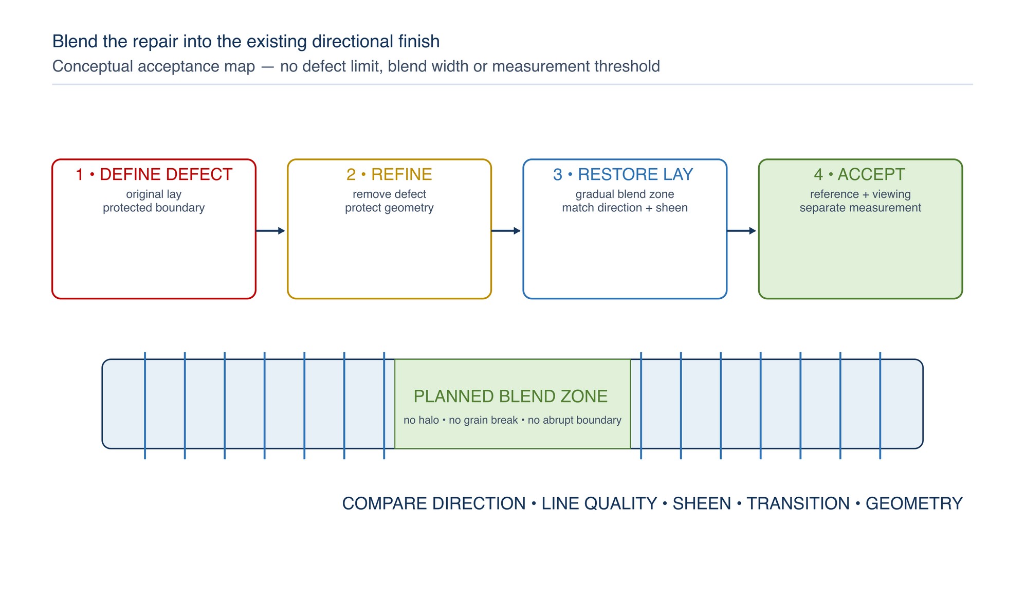
A local repair must reproduce the surrounding process character, not simply make the defect disappear. First remove the defect through an appropriate refinement sequence, then restore the final lay over a planned blend zone.
For directional stainless finishes, BSSA guidance recommends aligning and blending the new scratch pattern with the original and checking the resulting appearance. Work along the grain, use the finest suitable corrective stage, and avoid contaminating stainless work with tools previously used on carbon steel. [S125–S126]
Use this repair logic:
- define the defect, original lay and permitted blend boundary;
- protect unaffected faces and geometry;
- refine the defect without creating a hollow or bright island;
- widen the transition gradually rather than chasing a tiny spot;
- re-establish the final grain from the declared datum;
- clean away residue and inspect from several directions; and
- compare the repaired area with the accepted reference and surrounding panel.
Visual acceptance of directional finishes
Inspect the clean, dry surface under repeatable conditions unless the specification states otherwise. Use broad diffuse light for overall uniformity, low-angle light for hooks, grooves and waviness, and normal-use viewing for the customer-facing appearance.
Compare the workpiece and accepted reference under the same:
- light type and direction;
- viewing angle and distance;
- part orientation;
- cleanliness and dryness;
- protective-film condition, where relevant; and
- visible-area boundary.
Assess lay direction, line straightness, spacing, sheen, colour, transitions, local defects, edge condition and consistency across adjoining components. Photographs can support traceability but do not automatically replace a physical reference panel where appearance is critical. Any specified roughness, gloss, coating-readiness or functional measurement remains a separate acceptance check. [S105; S108; S117; S119–S120]
Troubleshooting directional-finish defects
| Symptom | Likely process cause | Practical correction |
|---|---|---|
| Grain wanders or curves | Weak datum, tool drift, hose drag, workpiece movement or belt-tracking error | Re-establish the datum, support the work, remove external drag and verify machine alignment |
| Hooks at the ends of strokes | Tool pivots during entry or exit; contact begins or ends abruptly | Use a planned lead-in and run-out, keep the path aligned and feather contact gradually |
| Bright or dark overlap bands | Pass spacing, contact width, wear state or pressure varies | Standardise the path step, contact attitude and product condition; reblend the full controlled zone |
| Rotary arcs remain in a linear finish lay | Disc pattern was not removed before the final process | Return to the last effective refinement stage and restore the directional grain with a suitable linear process |
| Repair halo or bright island | Blend zone is too small or the local process differs from the surrounding finish | Widen the transition gradually and match product construction, support, wear state and final direction |
| Finish changes at a weld or joint | Grain datum, support or process sequence changes across the transition | Plan one continuous final-lay sequence and inspect the joint under low-angle light |
| Streaks appear as the abrasive wears | Loading, damage, uneven wear, contamination or changed contact footprint | Stop, clean and inspect the interface; replace or condition the product as instructed |
| Surface smears or overheats | Excessive dwell or pressure, unsuitable speed, loaded abrasive or poor extraction | Restore effective cutting, reduce dwell and review the complete product-machine-material setup |
| Panels differ from each other | Starting surface, setup, path, consumable condition or viewing conditions vary | Standardise the full process and compare each panel with the same accepted reference |
Concise safety reminders
- Use only abrasive products and accessories intended for the material, machine, mounting and finishing task.
- Confirm compatibility between the abrasive dimensions and speed rating, accessory, machine and guarding arrangement.
- Secure the workpiece and maintain stable support, stance and line of fire.
- Keep guards, handles, extraction, interlocks and other protective systems in place as required.
- Control sparks, hot particles, combustible materials and metal dust through the workplace risk assessment.
- Wear eye and face, hearing, respiratory, hand, body and foot protection selected for the task.
- Stop for abnormal vibration, chatter, belt-tracking error, damaged backing, torn belts, heat, smearing, tool stall or unstable support.
- Keep hands, clothing, hair and cables away from abrasive contact, rotating parts and in-running nip points.
- Isolate energy before changing, cleaning, adjusting or inspecting abrasive products and machine components.
Refer to the product label, Technical Data Sheet, or MKTECH representative.
Application sequence
- Define the finish attributes, controlled zone, datum and accepted reference.
- Select a machine motion and abrasive form capable of producing the required lay.
- Protect edges, features and adjacent finished faces.
- Establish the planned entry, full-contact path, overlap sequence and exit.
- Confirm stable work support, tool condition, guarding and extraction.
- Set the process within the product and machine instructions.
- Make a representative pass and inspect direction, scratch character and sheen.
- Complete the surface in one planned progression without isolated reworking.
- Clean the surface and inspect under diffuse, low-angle and normal-use viewing.
- Blend transitions and repairs gradually while preserving geometry.
- Compare with the accepted reference and complete any specified measurement.
- Release the finish only when the pattern, transitions, appearance, geometry and functional checks pass.
Non-Woven Surface Conditioning
The Non-Woven Surface Conditioning chapter begins on the following page of the printed handbook (page 202), outside this chapter extract.