
Production engineers, supervisors, operators, QA/QC personnel, maintenance teams, fabricators, safety personnel, procurement staff and technical sales personnel
Practical selection and use of cutting and colouring compounds with stitched, loose-leaf, sisal, cloth/sisal and felt polishing tools in manual and automated metal-finishing operations.
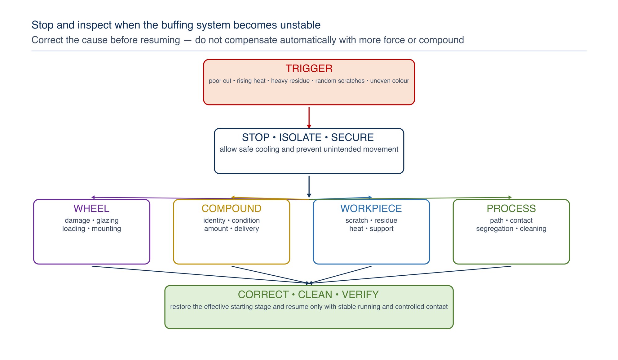
A compound or buff name is not an operating instruction. Verify the complete wheel construction, mounting, machine, guard, marked limits, work support and extraction. Never treat machine speed alone as the process setting and never exceed the lowest applicable marked limit. Stop immediately if vibration or irregular running develops, or if heat rises while useful cut falls, and do not cool a hot part by applying an unapproved liquid to a dry buffing operation. [S152; S155]
Core principle — The finish is produced by the compound–wheel–workpiece system. A compound or buff cannot be selected reliably in isolation.
This chapter explains how compound function, buff construction, contact behaviour and operating discipline combine to remove fine scratches, develop lustre and leave a clean surface ready for inspection or the next process.
Chapter objectives
After this chapter, the reader should be able to:
- distinguish cutting compounds from colouring compounds by process function;
- compare solid, paste and liquid delivery forms without relying on colour as a grade code;
- select a stitched, loose-leaf, sisal, cloth/sisal or felt tool for the required cut and geometry;
- apply enough compound to maintain effective action without overloading the wheel;
- control contact, speed, heat, residue and cross-contamination;
- clean and inspect the work between stages; and
- troubleshoot common compound-and-buff defects.
Treat compound and wheel as one abrasive system
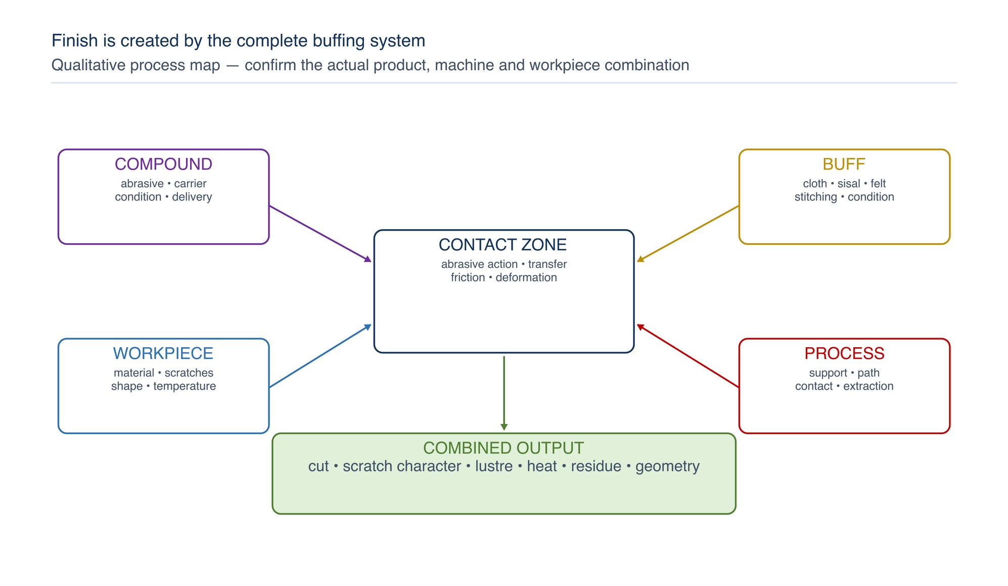
Conventional buffing brings together a rotating wheel, an abrasive compound, a machine, a supported workpiece and a controlled contact path. The compound supplies abrasive particles and a carrier; the wheel holds, distributes and works that compound at the surface. The workpiece material, starting scratch pattern, geometry and required appearance determine how the pair should behave. [S154]
Changing only one component can alter cut, heat, residue and visual result. A firmer wheel can make the same compound act more aggressively on a flat surface. A softer, more conformable wheel may reach a contour but reduce geometric control. Too little active compound can allow heat and glazing to rise; excessive application can coat the wheel, create fling-off and leave difficult residue.
Select the pair from five questions:
- What material and surface condition are entering the stage?
- Must the stage remove scratches, develop lustre, or do both?
- Which flats, edges, radii, recesses or details must be protected?
- What cleaning and downstream process follow buffing?
- How will appearance, cleanliness and any specified surface property be inspected?
Cutting and colouring are process functions
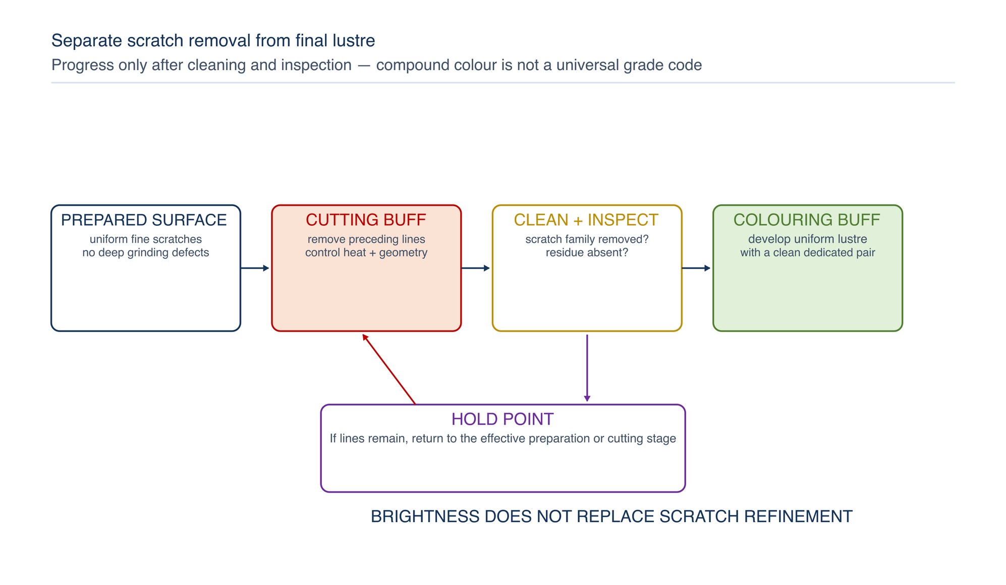
Most multi-stage buffing routes separate cutting from colouring. Cutting buffing removes the fine scratch pattern left by the preceding preparation stage and makes the surface smoother and more uniform. Colouring buffing uses a finer, gentler system to develop the final brightness or lustre. Some applications combine both functions, but the starting surface must still be suitable for the chosen system. [S154]
“Colouring” describes development of lustre; it does not mean applying a coloured coating. The visible colour of a compound bar is also not a universal grade system. Different manufacturers may use similar colours for different abrasive minerals, carriers or applications.
| Suitable entering condition | Compound function | Primary task | Release check | Wheel tendency |
|---|---|---|---|---|
| Previous scratch family removed without waves, heat damage or edge loss | Cutting | Remove fine preparation scratches and level small surface irregularities | Uniform, adequately refined surface with no deep grinding defects | Firmer or more cutting construction, selected for the geometry |
| Consistent surface whose remaining marks are within the system’s cutting capability | Cut-and-colour | Combine modest scratch refinement with brightness development | Uniform sheen with no persistent lines or local distortion | Balanced cut and compliance |
| Clean, well-refined pre-buff surface | Colouring | Develop high lustre and reduce very fine haze | Even colour and reflectivity after compatible cleaning | Softer, more conformable construction |
| Stable geometry and a prepared fine surface | Precision polishing | Produce a fine controlled paste finish on a compatible felt or other carrier support | Specified visual or measured result, checked separately | Shape-retaining or application-specific support |
Do not ask a colouring stage to repair a deep scratch. The surrounding area may brighten while the line remains, encouraging excess pressure, heat and edge rounding.
Understand compound forms without assuming equivalence
Industrial compounds may be supplied as solid bars, pastes, liquids or specialised slurries. The form controls how the compound is stored, applied, metered and cleaned; it does not by itself define cutting strength or finish quality. Distinguish cutting or pre-polishing compounds from final high-gloss polishing compounds by their declared duty. [S151; S158]
| Form | Typical production use | Main control points | Cleaning consideration |
|---|---|---|---|
| Solid bar | Manual application to a rotating cloth, sisal or felt tool | Brief, even presentation; avoid impact, prolonged loading and hand exposure to the contact zone | Waxy or greasy residue may collect in seams and recesses |
| Paste | Local manual work, felt tools, small features or precision polishing | Use a clean applicator; prevent drying, dilution or cross-mixing | Remove paste and spent abrasive before inspection or the next stage |
| Liquid compound | Metered manual, semi-automatic or automated delivery | Stable concentration, agitation where specified, clean lines/nozzles and even coverage | Overspray, mist, floor contamination and wastewater require control |
| Specialised slurry | Controlled polishing or lapping systems | Carrier compatibility, concentration, delivery, temperature and segregation | Slurry must not dry on the part or enter incompatible drains/processes |
Compound labels such as “coarse”, “fine”, “cut”, “colour” or a particular bar colour are meaningful only within the supplier’s system. For exact compound identity, substrate compatibility, application method and storage condition, Refer to the product label, Technical Data Sheet, or MKTECH representative.
Compound chemistry affects cut, heat and cleaning
A buffing compound normally combines abrasive mineral with a carrier that helps transfer and retain it at the wheel face. Carrier behaviour influences adhesion, lubrication, cooling, fling-off and the residue left on the part. The abrasive influences cutting action and scratch character. Because these functions are coupled, adding more compound does not necessarily produce more useful cut.
Spent compound can contain carrier, metal fines, abrasive debris and material transferred from the wheel. Heat may make residue more tenacious, particularly in corners, seams, pores and textured regions. Control application carefully because conventional compound residue can be difficult to contain and remove. [S154]
Choose the compound with the entire route in mind: substrate, wheel, required finish, cleaning method, coating or plating compatibility, product-contact duty and waste controls.
Wheel construction controls contact behaviour
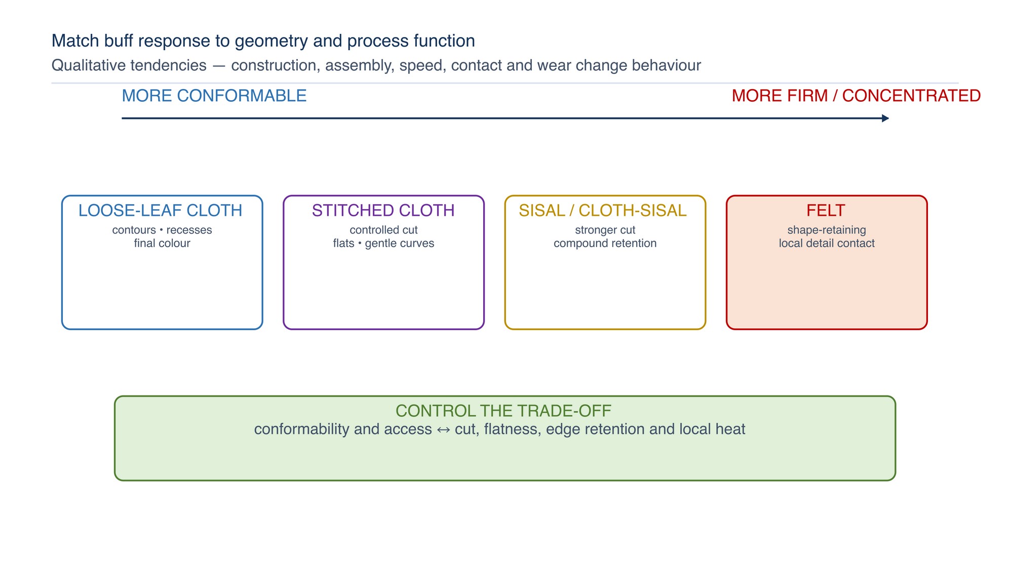
A buff is not simply a carrier for compound. Cloth grade, number and arrangement of plies, stitching, treatment, width, wheel condition and mounting all influence its effective firmness and ability to follow the work. Firmer stitched constructions resist deflection, while looser constructions conform more readily to shapes and contours. [S156; S157]
| Wheel family | General behaviour | Useful application tendency | Main caution |
|---|---|---|---|
| Stitched cloth | Firmer face; sewing restrains the plies | Cutting, flat or gently curved work, controlled edges and repeatable contact | Excessive local dwell can create heat, lines or geometry change |
| Loose-leaf cloth | Soft, flexible face; individual plies follow contours | Colouring, recesses, complex contours and final lustre | Can wrap around edges, catch projections or soften detail if poorly controlled |
| Sisal | Firm, aggressive natural-fibre construction with good compound retention | Cutting after suitable abrasive preparation on compatible metals | Not a universal final-colour tool; protect edges and control heat |
| Cloth/sisal combination | Intermediate firmness and compound retention | Balanced cutting and contour response | Construction varies widely; do not infer behaviour from appearance alone |
| Felt wheel or bob | Dense, shape-retaining carrier available in different forms | Small areas, edges, profiles, bores and fine or precision polishing with compatible paste | Concentrated contact can raise heat quickly or alter local geometry |
| Ventilated or pleated cloth | Folded construction with a compliant face and airflow between folds | Broad production work and contours where the construction suits the machine use | Direction, mounting hardware and product instructions govern |
Wheel “hardness” is therefore a practical system property, not a single cross-brand scale. A wheel that feels soft at rest may behave firmer at operating speed or when assembled into a wider pack.
Use stitched wheels for controlled cut
Stitched buffs restrain the cloth layers and create a more stable face than a loose-leaf assembly. Closer or more extensive stitching generally increases firmness; cloth grade and any treatment also influence the result. Firmer contact can improve cutting action and help preserve flats, but it also concentrates energy when the operator dwells or presents an edge incorrectly. [S156; S157]
Use a stitched construction when the stage must remove a controlled fine scratch pattern, maintain a broad contact band or resist excessive wrap. Keep the work moving through a planned path. Inspect the face for glazing, hard compound deposits, frayed cloth, loose stitching, imbalance or embedded debris before and during production.
Use loose-leaf wheels for conformity and colour
Loose-leaf buffs are assembled from flexible cloth discs with minimal restraint away from the centre. Their soft face can conform to irregular shapes and enter narrower details, which makes them useful for final colouring and light smoothing. [S156; S157]
That compliance also requires careful presentation. A projecting edge, slot or thin lip can enter between the plies and be pulled by the wheel. Work below the safe contact zone defined by the machine arrangement, support small parts securely and present edges so the wheel moves off the edge rather than into it. Avoid loose clothing, jewellery and gloves that could be drawn into the rotating assembly.
Use sisal and cloth/sisal where more cut is needed
Sisal is a natural fibre used in comparatively aggressive cutting buffs and is recognised for retaining compound. Alternating cloth and sisal can soften the contact and improve conformity while retaining useful cutting action. [S157]
Select sisal only after confirming that the entering scratch pattern, substrate and geometry suit a cutting-buff stage. It should not be used to compensate for incomplete grinding or coarse sanding. If the surface heats, tears, ripples or develops deep directional lines, stop and restore the preceding preparation rather than forcing the buffing stage.
Use felt for shape-retaining fine contact
Felt wheels, points and bobs provide a denser, more shape-retaining carrier than loose cloth. They are useful where a controlled face must work a small flat, edge, bore, groove, tool feature or local detail. Select the felt form, density and compound for the intended polishing duty. [S151; S159]
Felt concentrates contact on a smaller area, so heat and local removal can rise quickly. Shape the tool only by an approved method, keep it dedicated to one compound and material family where contamination matters, and replace it when embedded debris, glazing, damage or loss of geometry prevents controlled action.
Match wheel firmness to geometry and result
Select the least aggressive compound–wheel pair that can remove the entering scratch pattern while protecting the part.
- Broad flats: favour stable support and a controlled contact band; excessive softness can create waves.
- Outside curves and tubes: use enough compliance to maintain contact without flattening the radius.
- Inside radii and recesses: choose a form that enters the feature without rubbing adjacent faces.
- Edges, slots and projections: reduce wrap and keep the direction of wheel travel from pulling the feature into the nip.
- Fine details and tooling: use a shape-retaining felt or small supported tool, with short controlled contact.
- Final colour: use a clean, softer system only after the cutting pattern is fully removed.
Apply compound to maintain an active face
Compound should form a useful, renewed working film at the wheel face—not a thick layer that masks the cloth. Apply small, controlled amounts and judge the need for reapplication from cut, heat, wheel sound, surface appearance and residue. In automated systems, stable delivery also depends on clean tanks, lines and nozzles and the specified compound condition. [S154]
Signs of under-application can include falling cut, dry drag, rising heat or glazing. Signs of over-application can include heavy fling-off, a greasy wheel face, smeared residue, obscured scratches and difficult cleaning. These symptoms can have other causes, so stop and inspect the complete interface before adjusting delivery.
Never force a solid bar into the wheel or hold it in contact for an extended period. Keep hands clear of the nip and use the application method intended for the compound and machine.
Control speed, contact and movement together
Wheel diameter and rotational speed combine to determine surface speed. The correct operating range depends on wheel construction, mounting, compound, material, machine and workpiece geometry. Never treat machine speed alone as the process setting.
Confirm the marked limits and instructions for the actual wheel, attachment and machine. Refer to the product label, Technical Data Sheet, or MKTECH representative. Never exceed the lowest applicable marked limit.
Use stable contact and progressive movement. Excess force can collapse a soft wheel, increase the contact area unpredictably, heat the work and pull the part from its support. Very light contact may fail to engage the compound and encourage prolonged dwell. Establish the process on a representative sample, then maintain the same presentation, overlap and work path.
Manage heat before it changes the surface
Heat is generated by friction, abrasive cutting and deformation at the contact zone. Excess heat can discolour metal, distort thin parts, smear ductile alloys, bake compound onto the surface, damage the wheel and contribute to fire risk. Temperature control is therefore central to safe, repeatable buffing. [S154]
Control heat by maintaining an effective cutting face, using appropriate wheel compliance, moving continuously, limiting local dwell, supporting thin work and allowing the part and tool to cool when required. If heat rises while useful cut falls, stop.
Inspect for loading, glazing, insufficient compound, excessive compound, contaminated material, poor support or a stage mismatch.
Do not cool a hot part by applying an unapproved liquid to a dry buffing operation. Liquid use must be compatible with the machine, wheel, compound, substrate, electrical controls and downstream cleaning route.
Prevent compound and metal cross-contamination
Dedicate wheels and applicators by compound function and material family where carry-over can affect finish, corrosion performance, plating, coating, hygiene or precision service. A colouring wheel contaminated with cutting compound can introduce random lines. A stainless-steel buff exposed to carbon-steel particles can transfer iron contamination. [S151]
Use clear identification and covered storage. Keep cutting and colouring bars separate; do not press one compound onto a wheel already charged with another. Clean the work, fixtures, hands and surrounding area before moving to the next stage.
Where a compound or tool is changed, use a new or properly prepared carrier rather than relying on visual cleanliness alone.
Clean before inspection and downstream work
Inspect the finish only after removing compound residue with a method compatible with the substrate and next operation. Residue can hide fine scratches, collect in joints and interfere with coating, plating, bonding, welding, passivation or product-contact service. [S154]
Begin with the least aggressive effective cleaning method. Use clean, non-scratching wipes or brushes, provide access to recesses and prevent dirty cleaning media from redistributing abrasive particles. If an aqueous, alkaline, solvent or specialised cleaner is required, confirm material compatibility, rinsing, drying, ventilation, storage and waste controls from its Safety Data Sheet and process requirements.
After cleaning, inspect under consistent diffuse and low-angle light. Check scratch removal, uniform lustre, local waves, edge form, residue and transferred contamination separately. A bright surface is not proof that every functional requirement has been met.
Troubleshooting compound-and-buff defects
| Symptom | Likely system cause | Practical correction |
|---|---|---|
| Surface brightens but lines remain | Pre-buff preparation incomplete; colouring system has insufficient cut | Return to the effective preparation or cutting stage, restore a uniform scratch pattern, clean and progress again |
| Random deep scratches appear | Cutting compound or metal debris contaminated the wheel, work, fixture or cleaning media | Stop; segregate and replace contaminated items, clean the area and rework from the stage that removes the deepest line |
| Wheel face becomes greasy and cut falls | Compound over-application, loading or incompatible carrier/wheel pairing | Stop and inspect; remove excess by the approved wheel-maintenance method and resume with controlled application |
| Part becomes hot or discoloured | Excess dwell or force, concentrated contact, glazing, loading or unsuitable stage | Stop and cool safely; restore effective cut, support and movement before continuing |
| Uneven gloss or cloudy patches | Inconsistent pre-buff finish, wheel condition, compound delivery, overlap or cleaning | Standardise the entering surface and work path; clean fully and inspect under controlled light |
| Waves, hollows or softened edges | Wheel too compliant, contact too concentrated or repeated local dwell | Re-establish geometry with a firmer supported stage and protect critical transitions |
| Compound is flung around the station | Excess application, poor retention, incorrect presentation or unstable automated delivery | Reduce and stabilise delivery after checking the selected pair; improve containment and housekeeping |
| Residue remains in seams and recesses | Excess compound, heat-baked carrier or inadequate cleaning access | Reduce loading and heat; use a compatible cleaning method and appropriate non-damaging agitation |
| Wheel vibrates, frays or runs irregularly | Damage, contamination, incorrect assembly, uneven wear or incompatible mounting | Stop immediately, isolate the machine and inspect or replace the assembly before use |
| Finish changes between batches | Starting surface, compound condition, wheel wear, delivery or operator path has changed | Compare the complete process inputs and restore the approved combination and inspection conditions |
Concise safety reminders
- Inspect the wheel, stitching, centre, flanges, spindle, guard, machine and work support before use.
- Confirm wheel direction where marked and never exceed the lowest marked limit in the assembled system.
- Stand clear during start-up, allow the wheel to run without work contact, and stop immediately if vibration or irregular running develops.
- Secure the work and keep hair, clothing, jewellery, loose materials and hands away from rotating wheels and nip points.
- Use effective extraction or containment for compound dust, mist, fibres and metal particles; keep emissions away from the breathing zone. [S152]
- Review the compound and cleaner Safety Data Sheets and apply current Malaysian chemical-risk and exposure controls where relevant. [S153; S160]
- Assess combustible metal dust, lint and compound deposits; control ignition sources and clean the station using a method suitable for the collected material.
- Use suitable eye, face, hearing, respiratory, hand, body and foot protection for the complete task. Gloves must not introduce an entanglement hazard at rotating machinery.
- Isolate energy before mounting, dressing, cleaning, clearing, measuring or maintaining the equipment.
- Follow current site procedures, machine instructions and abrasive-product safety information. [S155]
Practical compound-and-buff sequence
- Identify the substrate, starting scratch pattern, geometry, contamination sensitivity and downstream process.
- Define whether the stage must cut, cut-and-colour, or colour, and establish the inspection reference.
- Select the least aggressive compound–wheel pair capable of the required result.
- Confirm wheel, mounting, machine, guard, marked limits, work support and extraction.
- Dedicate and identify wheels, compounds and cleaning materials by stage and material family.
- Clean the part and verify that the pre-buff surface is uniform and free of deep defects.
- Start the machine from a safe position and confirm stable running before work contact.
- Apply a small, controlled amount of compound using the intended method.
- Present the work with stable support, planned wheel travel, progressive movement and controlled overlap.
- Stop if heat, loading, vibration, heavy residue, grabbing or loss of cut develops; inspect before adjusting.
- Clean the part fully and inspect the cutting result before changing to the colouring stage.
- Use a clean dedicated colouring wheel and compound; do not carry cutting debris forward.
- Remove all residue using a compatible cleaning route and dry as required.
- Inspect appearance, cleanliness, geometry and any specified functional property separately; then protect the accepted surface and store the wheel and compound against damage or contamination.
Stainless-Steel Mirror Polishing
The next chapter, Stainless-Steel Mirror Polishing, begins on the following page of the printed handbook (page 237), outside this chapter extract.