
Production engineers, supervisors, operators, QA/QC personnel, fabricators, polishers, maintenance teams, safety personnel, procurement staff and technical sales personnel
A practical ten-stage route for producing and protecting a mirror-polished stainless-steel surface on accessible sheet, plate, tube, profile and fabricated components.
Inspect abrasives, wheels, compounds, machine, guards, mounting, work support and extraction before use. Confirm compatibility and never exceed the lowest marked operating limit in the assembled system. Secure the work and keep hair, clothing, jewellery, loose material and hands away from rotating contact and nip points. Stand clear during start-up and stop immediately if vibration, irregular running or product damage develops. Isolate energy before changing, mounting, dressing, cleaning, clearing or maintaining equipment. Use suitable eye, face, hearing, respiratory, hand, body and foot protection for the complete task. Gloves must not introduce an entanglement hazard at rotating machinery. [S152; S153; S160]
Core principle — Mirror polishing is an error-removal process. Every stage must remove the preceding scratch family while preserving the intended geometry; brightness alone does not prove completion.
This chapter integrates weld blending, abrasive refinement, compound polishing, final buffing, cleaning, inspection and protection into one controlled route. The exact combination depends on the starting surface, stainless-steel grade and condition, geometry, access, machine and required appearance.
Chapter objectives
After this chapter, the reader should be able to:
- define the required mirror appearance with an agreed reference and viewing conditions;
- plan the route from weld removal to protection without relying on a universal grit sequence;
- preserve flats, edges, radii and transitions while removing defects;
- recognise when a stage is complete before moving to a finer abrasive;
- use compound polishing and final buffing only after adequate preparation;
- clean, inspect and protect the finish without reintroducing scratches or contamination; and
- troubleshoot common mirror-polishing defects from the stage where they originated.
Define the mirror finish before starting
“Mirror” is a visual performance description, not a complete process specification. BSSA notes that nominally similar polished finishes can vary between suppliers and that grit designation alone does not fully define the result. ASSDA describes mirror finishes by high reflectivity, a substantially non-directional appearance and clear image formation, while recommending an agreed finished sample for critical work. [S161; S163]
Establish the acceptance basis before the first abrasive touches the part:
- the viewing side and all surfaces included in the finish;
- the required image clarity, uniformity and acceptable local variation;
- the agreed reference sample or first-off part;
- lighting type, intensity and direction;
- viewing distance, angle and part orientation;
- permitted edge softening, waviness, weld witness or local distortion;
- cleanliness and protection condition at final inspection; and
- any separate functional requirement for roughness, cleanability, corrosion service, coating, product contact or dimensional tolerance.
Do not use gloss, reflectivity or roughness as interchangeable terms. A surface may be bright yet retain rounded grinding furrows, waves, haze or isolated deep scratches.
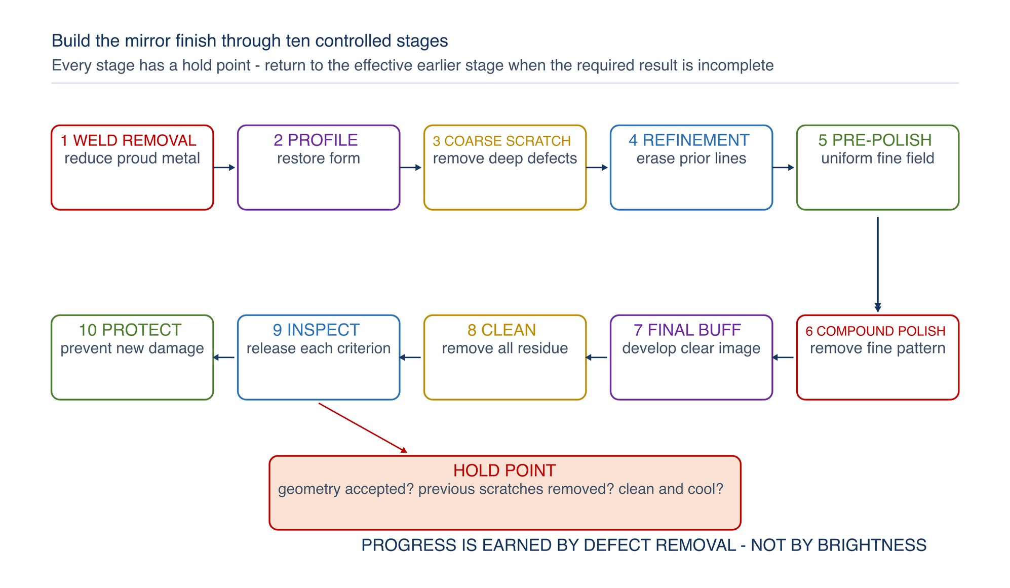
Plan the complete ten-stage route
The most economical route begins with the finest stage capable of removing the actual defect without excessive dwell. It then advances only after the current scratch family has been removed. Mirror finishing is a progression from defect removal through increasingly fine preparation to final buffing. [S162; S163; S164]
| Stage | Primary purpose | Completion signal | Main risk if rushed |
|---|---|---|---|
| 1. Weld removal | Reduce proud weld metal without undercutting the parent | Weld crown removed to the planned level; no gouge or heat surface damage | Low spot, flat spot, blueing or deep coarse lines |
| 2. Profile correction | Restore the intended flat, radius or transition | Reflected straightedge or contour appears continuous | Waves, edge roll-over or visible weld witness |
| 3. Coarse scratch removal | Remove grinding damage and establish a uniform starting pattern | Deepest prior lines and pits are absent | Deep marks carried into every later stage |
| 4. Progressive refinement | Replace each scratch family with a finer, uniform pattern | Previous-direction lines disappear under inspection | Mixed scratches, skipped-stage rework |
| 5. Pre-polishing | Produce a fine, even surface suitable for compound | Uniform low-haze surface with protected geometry | Buffing used to chase preparation defects |
| 6. Compound polishing | Remove the fine pre-polish pattern and begin image development | Fine lines removed; reflection becomes even | Heat, residue, waves or isolated compound scratches |
| 7. Final buffing | Develop final colour, lustre and image clarity under agreed conditions | Clean, uniform reflected image | Brightness hides residual furrows or haze |
| 8. Cleaning | Remove compound, abrasive and handling residue | Surface is residue-free without new scratches | False acceptance, staining or downstream interference |
| 9. Inspection | Verify appearance, geometry, cleanliness and specified function | All agreed checks pass independently | Release based on one viewing angle or gloss alone |
| 10. Protection | Prevent damage and contamination through handling and delivery | Suitable clean protection applied and identified | Scratches, adhesive residue, moisture entrapment or imprinting |
Remove weld metal without creating a hollow
Weld removal is geometry control before it is surface finishing. Support thin fabrications, use stable access and keep the contact path broad enough to blend the weld without dwelling beside it. Work progressively along the joint instead of cutting one local area to final level while neighbouring weld remains proud.
Stop frequently and inspect across the weld. A smooth-looking strip can still be low relative to the parent surface. Use reflection from a straightedge, flexible contour reference or controlled low-angle light to reveal hollows and flats. Protect adjacent edges, corners and formed radii from accidental contact.
Visible weld heat tint and contamination require appropriate post-weld treatment for the service condition. Mechanical finishing may be one part of the restoration route; chemical or electrochemical treatment must follow the applicable process information and workplace controls. [S166]
Correct profile before chasing fine scratches
Mirror surfaces reveal small geometric errors because reflected lines bend across waves, flats and softened edges. Correct form while the abrasive still has enough cut to do so efficiently. A later polishing mop can brighten a low spot but cannot restore lost thickness or a crisp transition.
Control profile by separating three tasks:
- Level: remove proud material without cutting below the design surface.
- Blend: spread the transition so the change in slope is visually continuous.
- Refine: replace the correction pattern only after the shape is accepted.
For sheet and broad flats, use backing and a travel pattern that limits local dwell. For tubes and outside curves, follow the radius without creating flats. For inside corners, choose a tool that reaches the feature without rubbing an adjacent face.
Inspect from more than one direction before releasing the profile stage.
Establish a uniform coarse scratch pattern
The first refinement stage must remove weld-grinding lines, pits, scale remnants, handling damage and other defects that would remain visible through the mirror finish. Begin with the least aggressive abrasive that can remove the deepest relevant defect at a controlled rate. A coarser starting stage may be necessary for severe damage, but it creates a deeper replacement pattern and increases later work.
Do not progress while isolated deep scratches remain. Marking the part with a removable inspection guide can help expose untouched areas, but the marking method must be compatible with stainless steel and the downstream process. Clean the surface before judging the scratch pattern so swarf or residue does not hide defects.
Refine scratches by making the previous pattern visible
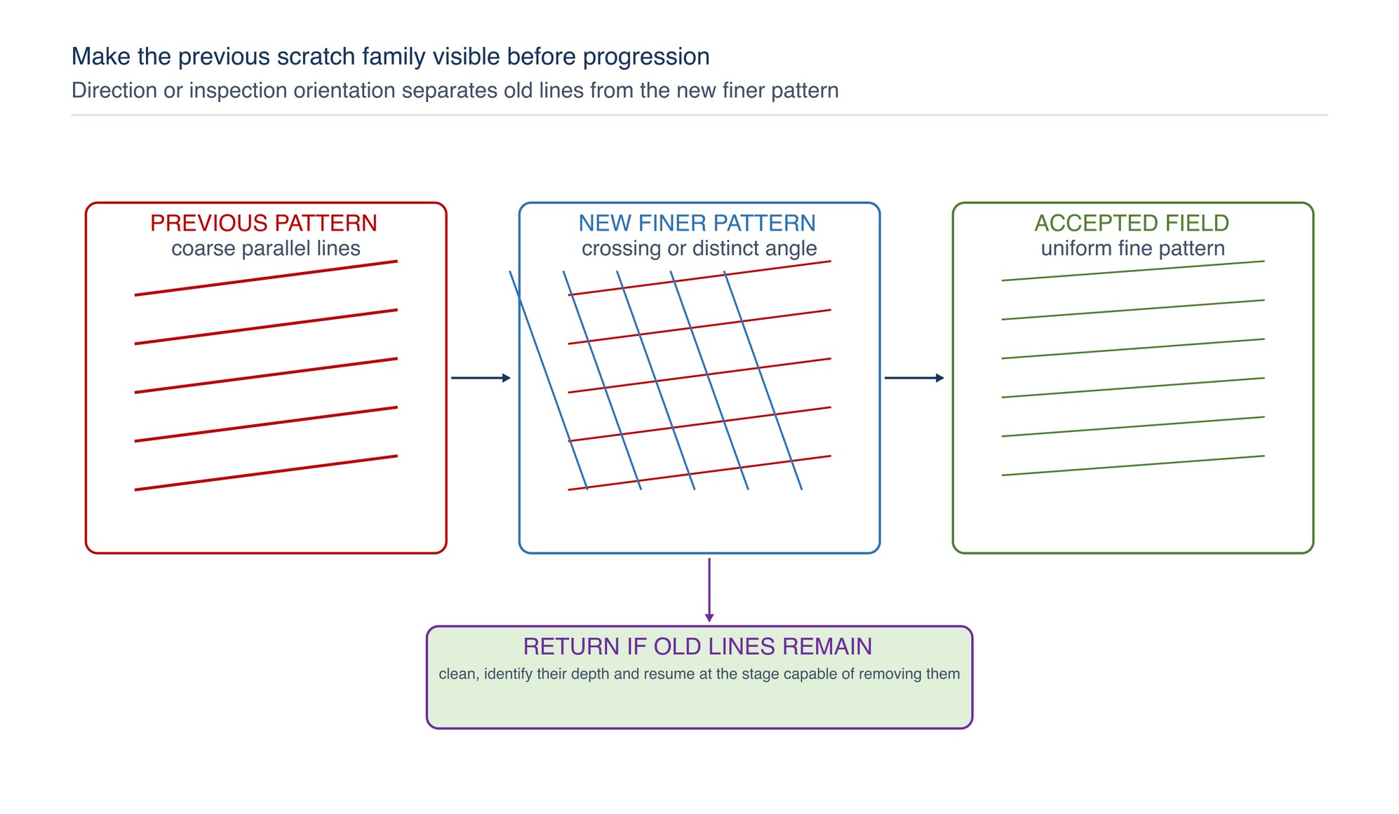
Successive refinement works only when the new stage removes the preceding pattern. Where geometry allows, change the working direction between stages so residual scratches cross the new pattern and remain visible. ASSDA identifies this direction change as a practical way to monitor removal. [S162]
On tubes, bowls or fixed assemblies where a ninety-degree change is impossible, alter the travel angle, overlap, lighting or inspection orientation enough to distinguish old lines from new ones. Clean the work, tool contact area and fixture between stages. One coarse particle carried forward can create an isolated line that becomes more conspicuous as the surrounding surface brightens.
Control stage size without treating grit numbers as universal
Abrasive grade is only one part of the stage. Grain type, grading system, backing, product construction, contact wheel, wear, speed, pressure, lubricant and workpiece response all affect the scratch produced. Therefore, a numeric sequence from one product family must not be assumed equivalent to another.
Use practical progression rules:
- avoid jumps that leave the next stage unable to remove the previous scratches efficiently;
- replace a worn, contaminated or damaged abrasive rather than relying on unpredictable glazing;
- use stable backing to protect flats and enough conformity to follow curves;
- reduce force if heat rises while useful cut falls;
- keep stage direction, overlap and coverage consistent; and
- confirm the result on a representative area before extending a revised route across the part.
For exact abrasive grade, machine compatibility, marked operating limit and intended use, Refer to the product label, Technical Data Sheet, or MKTECH representative.
Pre-polish to create a buffable surface
Pre-polishing is the bridge between coated or structured abrasives and compound polishing. Its purpose is to leave a fine, uniform surface that the compound–wheel system can complete without excessive pressure or dwell. The surface should show no coarse directional lines, pits, weld witness, local haze bands or embedded debris.
Before release to compound polishing:
- clean the part and surrounding work area;
- inspect under diffuse light for overall uniformity;
- use low-angle light to reveal furrows and waves;
- check edges and transitions for rounding;
- verify the part is cool and dry as required; and
- segregate pre-polishing media from compound-polishing and final-buffing media.
Use compound polishing to remove fine preparation lines
Compound polishing is still a cutting stage. Pair the compound with a wheel construction that provides enough cut to remove the pre-polish pattern while protecting the geometry. A firmer stitched cloth or suitable cutting construction may support broad flats and controlled cut; more conformable systems may suit contours. The actual pair must be compatible with the material, machine and required finish. [S151; S154]
Apply a small, controlled amount of compound and maintain progressive movement. Too little active compound can allow glazing and heat to rise; too much can create heavy residue, fling-off and obscured scratches. Clean and inspect before changing to the final buff. Do not carry cutting compound or embedded metal debris into the colouring stage.
Final-buff for colour and image clarity
Final buffing develops lustre and image clarity; it removes little material compared with the preceding abrasive stages. ASSDA warns that scratches left from grinding can remain as rounded furrows after buffing. [S163]
Use a clean, dedicated colouring wheel and compatible compound. Maintain light, stable contact and a planned travel path. Watch the reflected image rather than the shine alone: straight reference lines should remain straight across flats and change smoothly across intended curves. If a dark line, furrow or wave remains, stop and return to the stage capable of removing it.
| Before condition | What a false improvement looks like | Corrective route | Acceptable after condition |
|---|---|---|---|
| Proud weld with coarse grinding marks | Bright strip beside a remaining low spot | Level weld, restore profile, then refine | Continuous profile with no visible weld crown or hollow |
| Uniform fine preparation lines | Gloss rises but parallel furrows remain | Compound-polish with a controlled cutting pair | Lines removed and reflection beginning to resolve |
| Fine haze after cutting compound | Residue smears into temporary apparent gloss | Clean, inspect and final-buff with a dedicated colouring pair | Even colour and clear image under agreed light |
| Isolated deep scratch in a bright field | Narrow over-polished patch around the scratch | Return locally to the effective abrasive stage and re-progress a wide blend zone | Scratch removed without halo, dip or direction mismatch |
| Clear finish with handling marks | Cleaner residue or cloth marks visible at low angle | Compatible non-scratching clean and protected handling | Clean, dry, mark-free surface ready for protection |
Clean without scratching the finished surface
Mirror-polished stainless steel makes dust, fingerprints, cloth marks and cleaner residue highly visible. Remove compound with a method compatible with the substrate, compound and next operation. Start with the least aggressive effective method; use clean, non-scratching wipes or brushes and prevent dirty cleaning media from returning abrasive particles to the surface.
Clean seams, holes, recesses and fixture-contact areas. If a chemical cleaner is needed, confirm its material compatibility, rinsing, drying, ventilation, storage and waste controls. Never use carbon-steel wool or a pad previously used on carbon steel. [S125; S161; S165]
Inspect reflection, surface and geometry separately
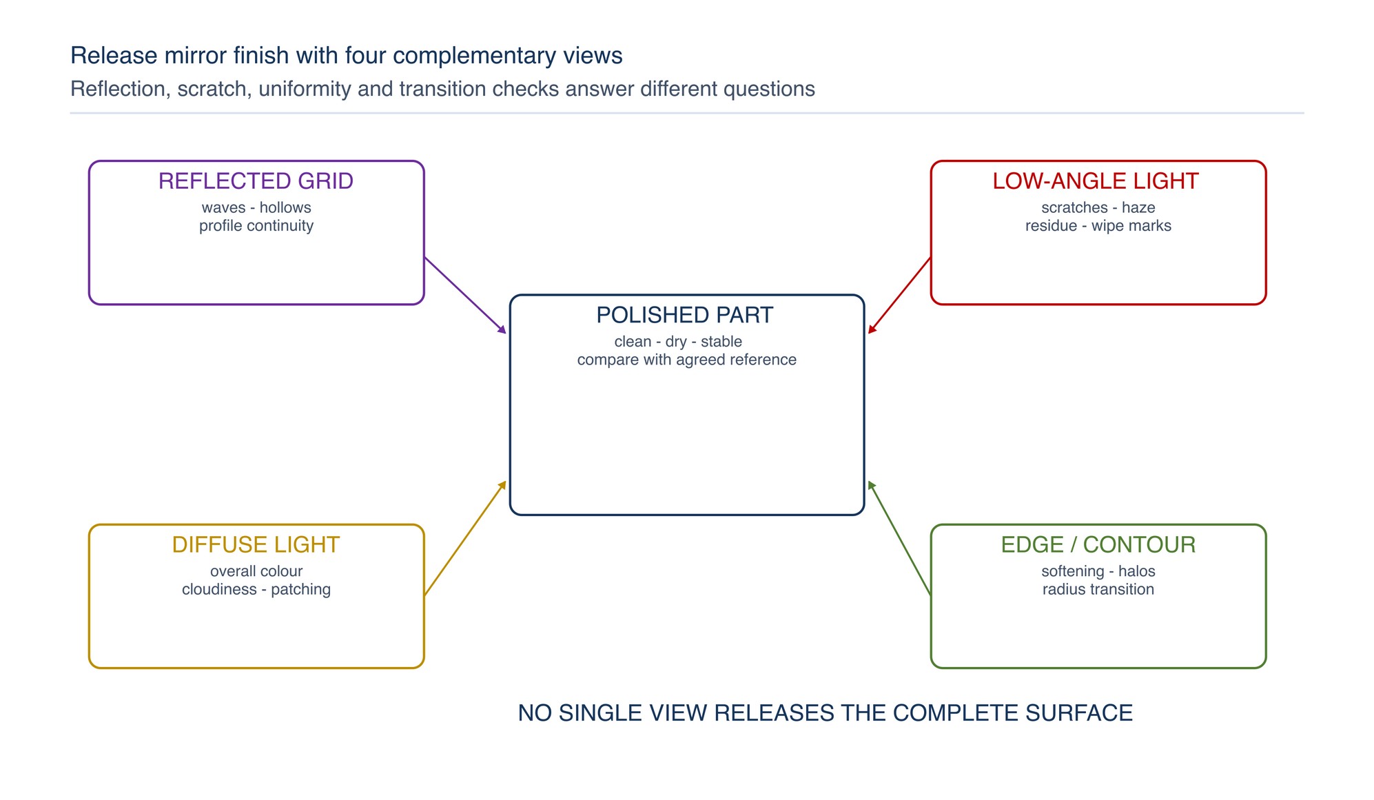
A reliable mirror-finish inspection uses more than one lighting condition and more than one viewing direction. A clear image can reveal waves, while low-angle light reveals furrows, haze and residue. Diffuse light helps judge overall uniformity. An agreed reference sample anchors the acceptance decision where appearance is critical. [S161; S163]
| Inspection mode | Reveals | Practical method | Do not confuse with |
|---|---|---|---|
| Reflected straight line or grid | Waves, flats, hollows and abrupt transitions | View a stable high-contrast line at several positions and angles | Surface brightness |
| Low-angle directional light | Fine scratches, furrows, haze and wipe marks | Sweep light across and along the last working directions | Dirt or temporary compound film |
| Diffuse broad light | Overall colour, cloudiness and local patching | Compare the complete part with the agreed reference | One favourable viewing angle |
| Edge and contour check | Softened edges, changed radii and blend halos across transitions | Inspect silhouette and reflection | Acceptable deliberate rounding |
| Cleanliness check | Compound in recesses, fingerprints, dust and cleaner residue | Inspect after compatible cleaning with clean gloves and lighting | Base-metal inclusion or pit |
| Specified measurement | Roughness, dimensions or other functional criterion | Use the specified instrument, location and acceptance rule | Visual mirror quality alone |
Protect the accepted finish immediately
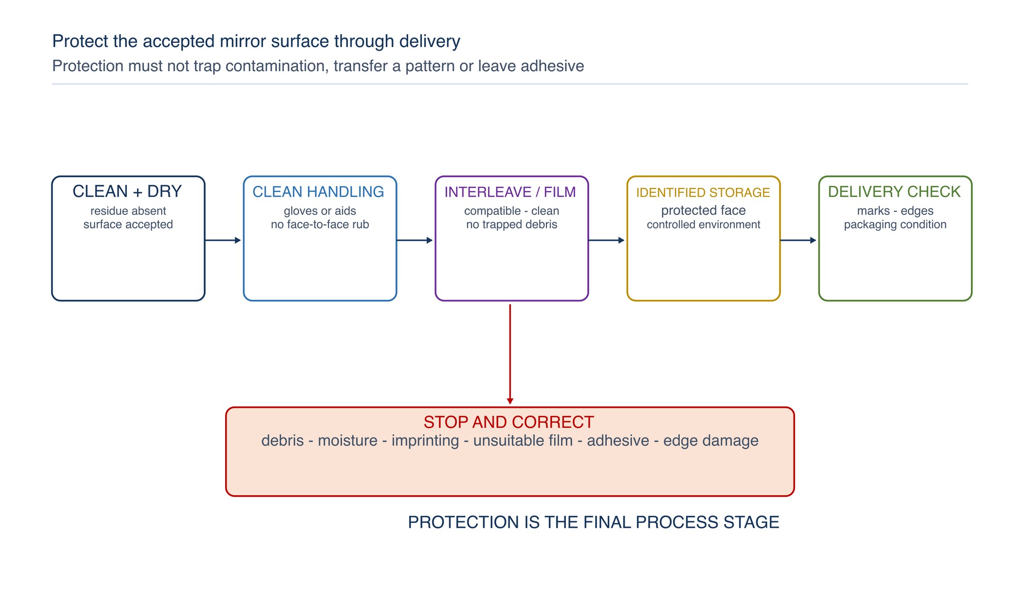
Highly polished stainless steel is susceptible to scratches, fingerprints, embedded particles and imprinting. Move the accepted part to a clean handling zone. Use clean gloves or non-marking handling aids, separate it from carbon-steel work and prevent finished faces from rubbing together.
Interleave parts with a clean, non-abrasive material that will not transfer a pattern. Where strippable film is suitable, confirm film compatibility, application cleanliness, storage conditions, service life, removal method and exposure limitations. IMOA notes that protective films can reduce scratching and contamination but can also deteriorate or leave adhesive if used outside their intended conditions. [S165]
Do not trap polishing residue, moisture or salts beneath protection. Identify the protected face and any removal instructions. Inspect again after packaging if the operation could have introduced pressure marks, trapped debris or edge damage.
Control contamination throughout the route
Use abrasives, wheels, compounds, fixtures, cleaning media and handling aids dedicated to stainless steel where iron contamination matters. Once an abrasive or wheel has contacted carbon steel, do not return it to stainless-steel mirror work. Keep grinding sparks and dust from nearby carbon-steel operations away from the polishing area. [S161; S165]
Segregate coarse and fine stages as well as material families. Store compounds covered and identified. Clean the machine, guards, rests and surrounding area before final polishing. Random deep lines in an otherwise refined surface often indicate contaminated media, embedded swarf or dirty cleaning materials rather than an insufficiently fine product.
Manage heat and distortion at every stage
Stainless steel can accumulate local heat during grinding and polishing. Thin sheet, edges and small contact zones are particularly sensitive. Heat can cause distortion, heat tint, smearing, compound baking and unpredictable scratch behaviour.
Control heat by keeping the abrasive cutting effectively, using appropriate contact support, moving progressively, limiting dwell and allowing the part and tool to cool when required. Stop if temperature rises while cut falls. Inspect for loading, glazing, excessive pressure, inadequate compound, contaminated media, poor support or an oversized contact zone before resuming.
Troubleshooting mirror-polishing defects
| Symptom | Likely system cause | Practical correction |
|---|---|---|
| Deep line remains after several fine stages | Earlier scratch not removed; contaminated abrasive or cleaning media | Return to the effective earlier stage, clean the system and re-progress over a broad blend zone |
| Surface is bright but image is distorted | Profile error, local dwell, soft support or edge roll-over | Restore geometry with controlled support before repeating refinement |
| Parallel furrows remain after final buff | Pre-polish or cutting-compound stage incomplete | Stop buffing and return to the stage that can remove the furrows |
| Cloudy or patchy reflection | Inconsistent starting pattern, wheel condition, compound delivery, overlap or cleaning | Standardise the entering surface and path; clean fully and inspect under diffuse light |
| Random scratches appear late | Coarse particle, metal debris, contaminated wheel, fixture or wipe | Isolate and replace contaminated items; clean the area and rework from the scratch depth |
| Part becomes hot or discoloured | Excess dwell or pressure, rubbing, loading, poor support or stage mismatch | Stop and cool safely; restore effective cut, support and movement |
| Edge becomes rounded | Excess wrap, soft support or repeated local contact | Use firmer support, protect the transition and widen the blend area |
| Compound smears or remains in seams | Over-application, heat-baked carrier or inadequate access | Reduce and stabilise application; use a compatible cleaning route with recess access |
| Finish changes between batches | Starting surface, abrasive condition, compound, wheel wear, path or inspection changed | Compare the complete process inputs with the approved reference and restore the controlled combination |
| Protection leaves marks or adhesive | Trapped debris, unsuitable interleaf or film used beyond its limits | Remove by the compatible method, re-clean and use validated protection conditions |
Concise safety reminders
- Inspect abrasives, wheels, compounds, machine, guards, mounting, work support and extraction before use.
- Confirm compatibility and never exceed the lowest marked operating limit in the assembled system.
- Secure the work and keep hair, clothing, jewellery, loose material and hands away from rotating contact and nip points.
- Stand clear during start-up and stop immediately if vibration, irregular running or product damage develops.
- Control grinding dust, polishing debris, wheel fibres, compound particles and cleaning vapour at source. [S152; S153; S160]
- Review compound and cleaner Safety Data Sheets and apply current Malaysian chemical-risk controls.
- Control combustible lint, metal dust and compound deposits; keep ignition sources away and clean using a method suitable for the collected material.
- Use suitable eye, face, hearing, respiratory, hand, body and foot protection for the complete task. Gloves must not introduce an entanglement hazard at rotating machinery.
- Isolate energy before changing, mounting, dressing, cleaning, clearing or maintaining equipment.
- Follow current site procedures, machine instructions and abrasive-product safety information. [S155]
Practical mirror-polishing sequence
- Confirm the material, component geometry, service condition and agreed mirror-finish reference.
- Identify weld crown, heat tint, pits, coarse scratches, distortion and contamination before selecting the starting stage.
- Secure and support the work; establish safe access, extraction and handling controls.
- Remove proud weld metal without cutting below the parent surface.
- Correct the profile and approve flats, radii, edges and transitions before fine refinement.
- Establish a uniform scratch pattern that removes the deepest relevant defects.
- Progress through finer stages, changing or distinguishing direction and cleaning between stages.
- Release pre-polishing only when the surface is uniformly fine, cool, clean and free from coarse lines.
- Compound-polish with a compatible cutting pair until the preparation pattern is removed.
- Clean and inspect before changing to a dedicated final-buffing pair.
- Final-buff for even colour and image clarity without chasing deep defects.
- Remove all residue using a compatible non-scratching method and dry as required.
- Inspect reflection, scratches, geometry, cleanliness and any specified measurement independently under agreed conditions.
- Protect the accepted surface immediately with clean handling, compatible interleaving or film and identified storage.
Polishing Defects
The Polishing Defects section appears on the following page of the printed handbook (page 246), outside this chapter extract.