
Production engineers, paint-shop supervisors, process engineers, maintenance teams, QA/QC personnel, safety and environmental personnel, procurement staff and technical sales personnel
A practical method for selecting dry paint-booth overspray filters from verified process conditions, declared product data and whole-system constraints.
Select the filter as part of the booth system. The correct option must capture the relevant overspray, hold the expected paint load, preserve the required airflow, fit the installed frame, remain compatible with the coating and follow an acceptable waste route at a sustainable total operating cost.
Do not correct an unsuitable filter by increasing fan speed beyond the booth's approved operating method. This may change containment, turbulence, motor load, noise, discharge behaviour and fire protection. Stop spraying for loss of containment, abnormal pressure, collapse, run-off, breakthrough, heat, smoke or smouldering odour. Treat used filters according to the captured residue and Malaysian waste requirements.
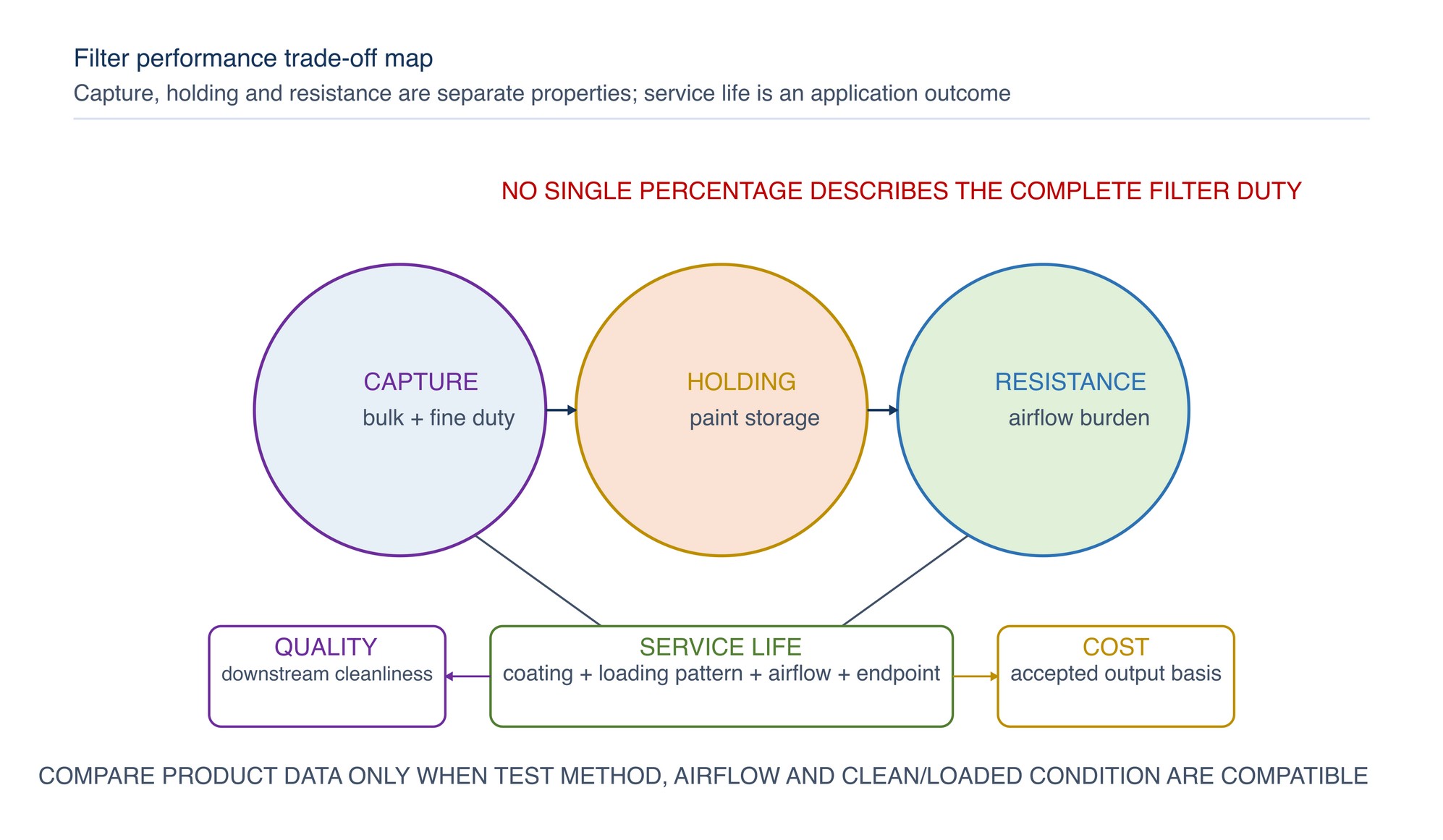
Filter selection is not a search for one highest percentage. Every dry arrestor represents a balance among droplet capture, paint-holding capacity, airflow resistance, physical integrity, service life and cost. A media that performs well in a low-rate intermittent booth may block prematurely in continuous high-solids production. A coarse high-capacity stage may control bulk wet overspray but require a downstream stage where fine mist or sensitive equipment must be protected. [S178; S192; S193]
This chapter develops the selection route introduced in Chapters 032 and 033. It is an educational and application-selection guide. The installed booth design, coating Safety Data Sheet, applicable Malaysian requirements and current product documentation remain controlling. Where an exact product value is required, Refer to the product label, Technical Data Sheet, or MKTECH representative.
Chapter objectives
After this chapter, the reader should be able to:
- define the selection duty from paint type, solids content, spray rate and overspray volume;
- convert booth airflow and effective filter area into a meaningful face-velocity condition;
- distinguish overall arrestance, size-dependent capture, holding capacity, resistance and service life;
- establish the available resistance allowance without destabilising the booth;
- decide when a single-stage, backed or multi-stage arrangement should be evaluated;
- screen coating compatibility, fire behaviour, handling and Malaysian disposal requirements;
- compare operating cost on an accepted-production basis rather than purchase price alone;
- use a complete decision tree to produce a technically defensible shortlist; and
- recognise field symptoms that indicate the selected system is unsuitable or incorrectly applied.
Define the duty before choosing the media
Begin with the normal production condition, not an empty booth with clean filters. The filter must receive the actual coating cloud generated by the spray equipment, part geometry, painter or robot path, transfer efficiency, output and booth airflow.
The selection record should describe the process in observable terms that another engineer can verify.
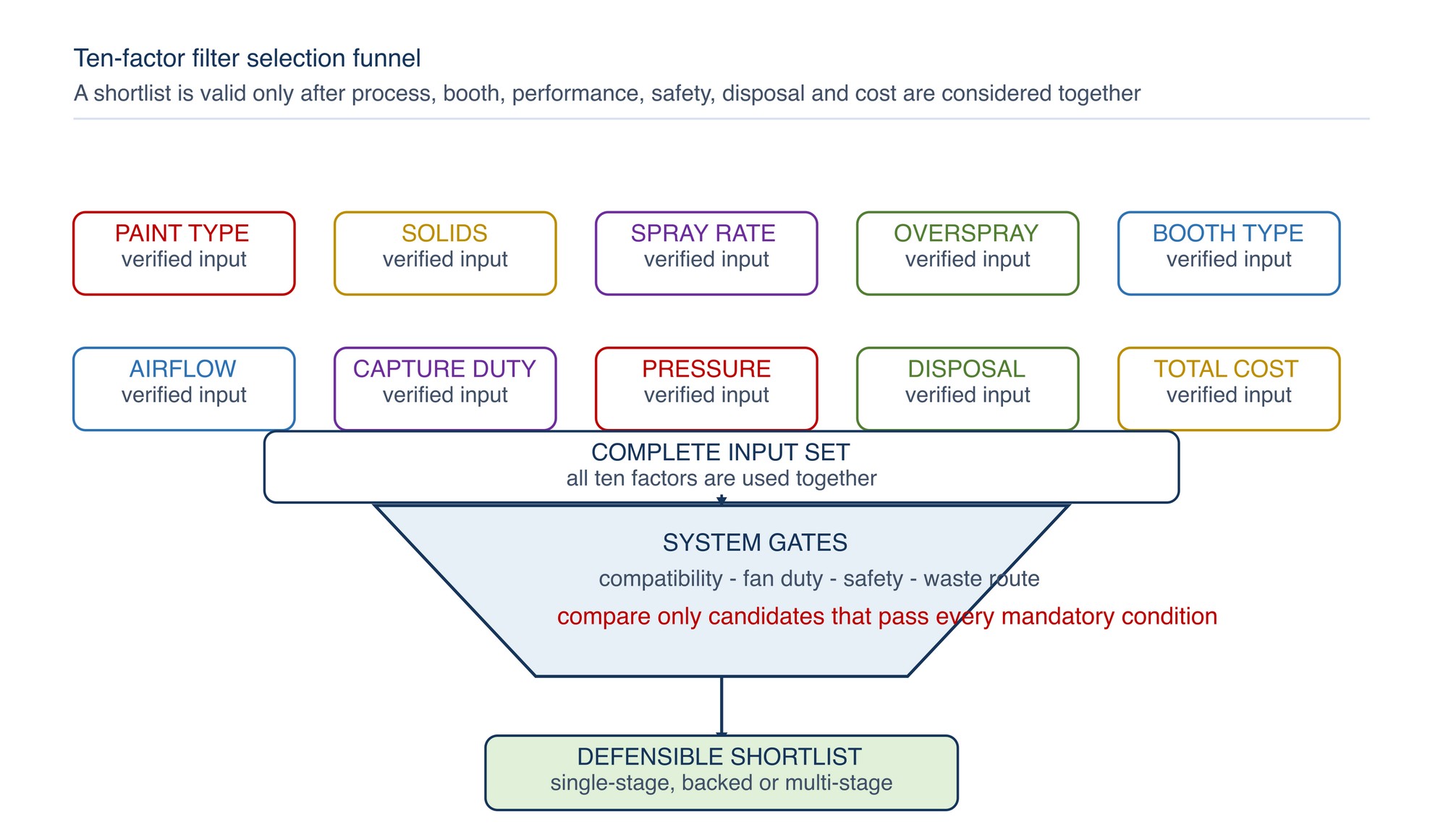
| Selection factor | Define in practical terms | Why it changes the choice | Verification source |
|---|---|---|---|
| Paint type | Solvent-borne, water-reduced, two-component, adhesive, gel coat or other declared system | Changes droplet behaviour, wet strength, residue compatibility and fire/waste controls | Coating label, SDS and TDS |
| Solids content | Declared mixed or ready-to-spray condition | Influences deposited mass, tack, bridging and holding demand | Coating TDS and mix record |
| Spray rate | Normal and credible peak application rate | Establishes how quickly mass reaches the bank | Equipment setting and production observation |
| Overspray volume | Material not deposited on the workpiece that reaches the exhaust face | Determines bulk capture and storage demand | Material balance, transfer condition and booth inspection |
| Booth type | Crossdraft, semi-/side-downdraft, downdraft or engineered variant | Changes loading distribution, filter orientation and effective area | Booth drawing and physical survey |
| Airflow | Normal flow through the occupied booth and filter bank | Governs transport, face velocity and filter resistance | Commissioning or verified measurement |
| Required capture requirement | Downstream cleanliness, permit, equipment or process duty | Determines whether coarse capture or staged fine capture is needed | Regulatory, booth and process requirement |
| Resistance allowance | Pressure available across clean and loaded filtration stages | Limits usable media and stage combinations | Fan/system information and pressure profile |
| Disposal route | Classification, segregation, storage and authorised destination | Affects material choice, handling and total cost | Coating/process information and DOE requirements |
| Operating cost | Media, labour, disposal, energy, cleaning and quality consequences | Prevents low unit price from hiding high process cost | Purchasing and production records |
Characterise the paint and overspray
Paint type is the first technical branch because the clean filter never operates alone; it becomes a paint-loaded composite.
Check the mixed coating, hardener, thinner, cleaning materials and any alternation between products. The complete media construction includes paper or fibre, binder, adhesive, backing, frame and surface treatment.
| Paint behaviour | Likely filtration demand | Media feature to evaluate | Do not assume |
|---|---|---|---|
| Large wet droplets | Internal storage and run-off control | Open labyrinth, pocket or high-loft first stage | A finer face automatically gives longer life |
| Fine atomised mist | Declared fine stage or multi-stage system | Improved small-droplet capture | Overall mass arrestance proves fine-particle capture |
| High-solids coating | High deposited mass and possible bridging | High holding volume and even full-bank loading | High solids always means large droplets |
| Water-reduced coating | Moisture exposure and different drying behaviour | Declared wet strength and compatible adhesive/backing | Paper colour or thickness proves moisture resistance |
| Two-component reactive material | Continued curing and possible heat generation in residue | Compatible media and segregated handling | Loaded filters share the clean media's fire behaviour |
| Highly tacky adhesive or gel coat | Face skinning and blocked openings | Open first-stage geometry and adequate storage | A dense single pad will load through its full depth |
| Fast-drying or friable deposit | Surface cake, shedding or re-entrainment | Stable depth media and downstream protection | A filter suitable for wet mist suits dry particulate |
| Frequent chemistry changes | Cross-contamination and incompatible residue | Dedicated banks, compatible construction or controlled change sequence | One bank can alternate safely among all coatings |
Solids content is not a filter-efficiency value. It is one contributor to the mass that may reach the exhaust. Spray rate is also not overspray volume: a high-rate efficient application can place less material on the bank than a lower-rate application with poor transfer or difficult part geometry. Treat the three quantities separately.
Estimate the loading duty
The most useful loading description combines deposited mass, time and distribution. Exact paint capture may require a controlled material balance, but a sound first selection can be formed from normal consumption, transfer condition, production duration and filter inspection.
Use the relationship conceptually:
Overspray load reaching the bank = coating used - coating deposited on acceptable work - other controlled losses
Do not substitute a generic transfer-efficiency percentage. Part size, recesses, gun distance, fan pattern, robot path, painter technique, colour change and reclaim practices can materially change the result.
Classify the duty for selection:
- Light/intermittent: long non-spray periods, modest daily mass and limited local loading.
- Moderate/repeating: regular batches with predictable full-bank loading.
- Heavy/continuous: sustained application or high mass requiring substantial internal capacity.
- Concentrated/local: one zone receives a disproportionate load because of work position or spray direction.
- Mixed droplet: bulk wet overspray and fine mist reach the bank together.
The category is a communication aid, not a performance rating. Define it with actual production information and revise it when the coating, equipment, part family or work method changes.
Establish the booth and airflow constraint
The same filter can behave differently at different airflow conditions. Air must carry overspray from the work zone to the exhaust face, pass through the installed media and remain within the fan/system capability. Filter-face velocity depends on the flow through the bank and the effective open filter area.
Filter-face velocity = airflow through the bank / effective filter area
Use consistent units and exclude blocked frames, sealed-off zones and non-flow area from the denominator. Average velocity alone is not enough: a partially bypassed or uneven bank can contain high local velocity beside stagnant loading zones. [S171; S172; S194]
| Booth/system condition | Selection consequence | Confirm before shortlisting |
|---|---|---|
| Crossdraft with full rear-wall bank | Loading may reflect part wake and gun direction | Effective bank area, perimeter seal and distribution |
| Downdraft with floor or pit filters | Gravity, floor geometry and local wet load affect distribution | Support, access, run-off control and plenum condition |
| Side- or semi-downdraft arrangement | Multiple paths can load asymmetrically | Flow balance and representative pressure points |
| Fixed-speed fan | Added resistance commonly reduces airflow | Fan curve, clean baseline and loaded operating limit |
| Controlled-flow fan | Control may increase fan effort as filters load | Available control range, motor capacity and alarm logic |
| Limited frame depth | Restricts pockets, cubes or added stages | Installed dimensions, support and service clearance |
| Small effective filter area | Raises face velocity for a given flow | Area calculation and local loading pattern |
| Existing dirty duct or blocked plenum filter | Consumes pressure allowance outside the filter | System pressure profile and cleaning condition |
Do not correct an unsuitable filter by increasing fan speed beyond the booth's approved operating method. This may change containment, turbulence, motor load, noise, discharge behaviour and fire protection. Selection must fit the complete system.
Define capture performance correctly
Required efficiency should state what must be captured, under which test or service condition and for what downstream purpose. EPA research shows that overall mass arrestance and penetration by droplet size describe different aspects of overspray-arrestor behaviour. A high mass percentage can be dominated by large droplets while a small mass of finer droplets still penetrates. [S192; S193]
Ask five questions whenever a performance percentage appears:
- What test method or verified service method produced it?
- What challenge aerosol, coating or particle-size distribution was used?
- At what airflow or face-velocity condition was the filter tested?
- Was the result measured clean, loaded or across a defined loading sequence?
- Does the figure apply to one layer, a complete composite or the installed multi-stage system?
| Property | What it describes | Selection use | Common error |
|---|---|---|---|
| Overall mass arrestance | Fraction of challenge mass retained | Bulk paint control under stated test conditions | Treating it as fine-droplet efficiency |
| Fractional efficiency or penetration | Capture or passage by particle-size band | Downstream fine-mist sensitivity | Comparing values from different test methods |
| Paint-holding capacity | Mass retained before a stated endpoint | Change-out frequency and first-stage duty | Assuming more capacity always means lower resistance |
| Initial resistance | Pressure loss of clean media at a stated airflow | Clean-system pressure budget | Comparing products at different velocities |
| Final or recommended resistance | Declared endpoint under stated conditions | Change-out planning and fan-system fit | Using it as a universal booth limit |
| Service life | Operating period before the actual endpoint | Cost and maintenance planning | Treating supplier or another site's life as guaranteed |
General-ventilation ratings are not automatically overspray-arrestor ratings. Compare only declared paint-arrestor data that match the intended coating and airflow condition. Refer to the product label, Technical Data Sheet, or MKTECH representative.
Build the pressure-drop allowance
The filter receives only part of the fan's total pressure capability. Intake filters, diffusers, enclosure openings, exhaust filters, ducts, dampers, discharge fittings and dirty surfaces all contribute resistance. The available allowance must be established from the actual system pressure profile and acceptable airflow range. [S171; S179; S180]
Use this sequence:
- Verify the normal production airflow and containment condition.
- Confirm the current fan, drive, control mode, damper and motor state.
- Measure or obtain the clean-system pressure profile at defined points.
- Separate intake, booth, exhaust-filter and downstream-system losses where practical.
- Determine the earliest allowed endpoint from airflow, containment, fan/motor, filter, physical and fire controls.
- Reserve margin for realistic loading and measurement variation.
- Evaluate the proposed first, intermediate and final stages as one combined system.
Adding pressure losses arithmetically is valid only when the values refer to the same airflow and compatible test conditions. Media resistance normally changes with airflow, loading and installation. Do not add a clean value at one velocity to a loaded value at another and present the result as a system prediction.
| Pressure-budget question | Acceptable evidence | Selection decision |
|---|---|---|
| What is the clean baseline? | Verified installed pressure and airflow after a sealed change | Establish normal starting condition |
| What airflow must be maintained? | Booth method, commissioning basis or verified process requirement | Set the operational boundary |
| How does the fan respond to loading? | Fan/system information and observed trend | Determine whether flow falls or control effort rises |
| Which stage causes the resistance? | Pressure points across individual stages where provided | Select staged change-out instead of replacing everything |
| What is the physical endpoint? | Sag, collapse, tearing, run-off, bypass or downstream breakthrough | Replace before pressure alone reaches a limit |
| What exact product limit applies? | Refer to the product label, Technical Data Sheet, or MKTECH representative. | Current declared product information |
Choose the system architecture
Use a single stage when one declared construction can provide the required bulk capacity and downstream protection within the available resistance and frame arrangement. Use a backed or multi-stage system when coarse wet load and fine-mist capture impose conflicting duties, or when downstream sensitivity justifies a separate final stage.
| Duty pattern | Architecture to evaluate | Main benefit | Main risk to control |
|---|---|---|---|
| Light, broad droplet range and tolerant downstream | Single declared paper or depth-media stage | Simple installation and change-out | Insufficient fine capture or short life if duty increases |
| Heavy wet bulk load | High-capacity inertial or open-depth first stage | Stores paint away from the face | Run-off, local overloading and downstream penetration |
| Bulk load plus fine mist | Coarse/high-capacity stage followed by depth stage | Divides storage and final-capture duties | Added resistance and poor interstage sealing |
| Sensitive fan, heat exchanger or discharge duty | Staged system with declared final protection | Reduces downstream deposit | Final stage can block rapidly if first stage fails |
| Frequent product or colour changes | Modular easily changed first stage with compatible support | Controlled housekeeping and segregation | Excess waste volume or chemistry mixing |
| Limited frame depth or fan margin | Compact declared construction | Fits physical and pressure constraints | More frequent changes or reduced storage capacity |
A downstream stage is not permission to leave a failed first stage in service. If bulk paint reaches the fine stage, resistance may rise quickly and the complete bank can lose airflow.
Screen compatibility, safety and disposal
No option proceeds to cost comparison until it passes the compatibility and safety screen.
Reject or escalate a candidate when:
- the supplier does not declare it suitable for the coating or moisture condition;
- the complete media construction can soften, shed, collapse or react in service;
- the coating residue is susceptible to self-heating and the arrangement is not specifically suitable;
- incompatible coatings would accumulate in the same bank or container;
- the booth's fire-protection, interlock or access arrangement cannot be maintained;
- the media cannot be installed in the intended direction with continuous support and sealing;
- used filters cannot be safely handled, classified, contained or sent to an authorised destination; or
- changing the filter system would compromise an applicable permit, booth approval or engineering control.
OSHA's dry-filter provisions are used here as transferable safety principles: airflow indication, filter inspection, control of discarded media, protection around the filter area and prevention of incompatible or self-heating residues. Malaysian requirements and the authority having jurisdiction govern the installation. [S175; S185]
In Malaysia, the waste producer classifies the used filter from the generating process and captured materials. Disposal cost and handling effort therefore depend on the residue, segregation plan, container and authorised route—not only the clean media mass. [S188; S189]
Compare total operating cost
Unit price is visible; process cost is distributed. Compare candidates over a common production basis such as accepted parts, coated area, production hours or coating throughput. Use the measure that best represents value at the site.
Total filter-system cost = media + change labour + disposal + energy + cleaning + filtration-related quality loss
Keep the comparison transparent. If a cost cannot be isolated reliably, record how it was estimated and avoid presenting it as a guaranteed saving.
| Cost element | What to count | Frequent omission |
|---|---|---|
| Media | Complete first, intermediate and final stages | Support grids, clips or special frames |
| Change labour | Isolation, removal, cleaning, installation and verification | Lost production and post-change checks |
| Disposal | Containers, labels, storage, transport and authorised treatment | Residue-specific segregation |
| Energy | Fan input over the actual resistance profile | Comparing only clean-filter resistance |
| Booth cleaning | Plenum, duct, fan and surrounding overspray cleanup | Breakthrough caused by bypass or weak final capture |
| Quality | Dust nibs, dry spray, uneven finish, rework and rejected output linked to filtration | Blaming every coating defect on the filter |
| Inventory | Stockholding, storage life, roll offcuts and emergency supply | Obsolete or incompatible grades |
Use the complete selection decision tree
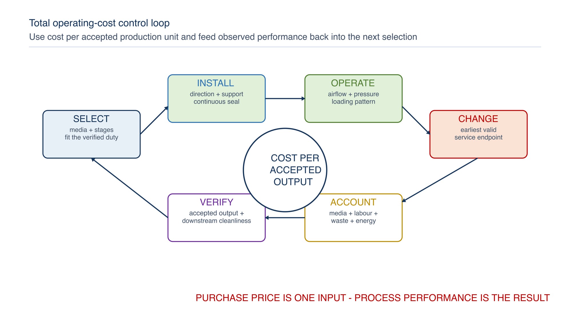
The following decision tree converts the ten required inputs into a shortlist and release path.
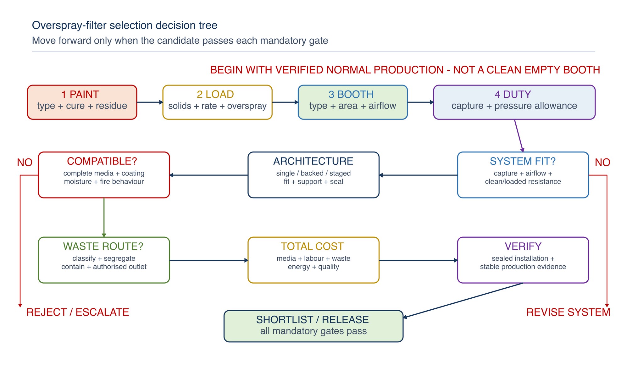
Apply the tree in this order:
- Identify the paint system. Confirm mixed coating, carrier, cure chemistry, tack and residue hazards.
- Define solids and spray rate. Use the normal condition and credible peak, not only nominal equipment capacity.
- Estimate overspray volume and pattern. Distinguish total mass from local concentration and fine mist.
- Confirm booth type and effective filter area. Establish frame depth, support, access and loading distribution.
- Verify airflow and fan response. Use the occupied normal production arrangement.
- Define capture duty. State downstream protection and the comparable test basis needed.
- Set the resistance allowance. Evaluate clean and loaded stages within the complete fan/system condition.
- Choose architecture. Shortlist single-stage, backed or staged media families.
- Pass safety and disposal gates. Confirm compatibility, fire controls, segregation and Malaysian waste route.
- Compare operating cost. Use accepted production and observed change-out evidence.
- Verify installation and production behaviour. Release only after the sealed bank provides stable airflow, containment and downstream cleanliness.
Compare candidates on one basis
Use a structured shortlist so one attractive property cannot hide a system failure.
| Comparison field | Candidate A | Candidate B | Candidate C |
|---|---|---|---|
| Declared coating/application | Record exact declared duty | Record exact declared duty | Record exact declared duty |
| Construction and stages | Media family and support | Media family and support | Media family and support |
| Test basis for capture | Method, challenge and airflow | Method, challenge and airflow | Method, challenge and airflow |
| Clean and change limits | Comparable declared conditions | Comparable declared conditions | Comparable declared conditions |
| Holding/load evidence | Test basis or controlled service trend | Test basis or controlled service trend | Test basis or controlled service trend |
| Installed fit and seal | Frame, direction and access | Frame, direction and access | Frame, direction and access |
| Safety/compatibility | Pass, reject or escalate | Pass, reject or escalate | Pass, reject or escalate |
| Waste route | Classification and container | Classification and container | Classification and container |
| Cost basis | Cost per accepted-output unit | Cost per accepted-output unit | Cost per accepted-output unit |
| Decision | Reasoned outcome | Reasoned outcome | Reasoned outcome |
Do not score a mandatory safety, compatibility or legal requirement. It is a pass/reject gate. Weighted scoring is suitable only for remaining commercial and operational differences after all mandatory conditions pass.
Verify the shortlist in production
A controlled evaluation confirms system behaviour without claiming a universal product ranking. Keep the coating, booth, part family, application method and production basis comparable.
Record:
- exact filter identity, construction, stages, orientation and installed area;
- coating and mix condition, spray equipment and representative production output;
- clean pressure, airflow/containment condition and fan/control state;
- loading distribution, run-off, sag, damage, bypass and downstream deposits;
- change-out trigger and production achieved before that trigger;
- labour, waste container and disposal route;
- finish defects or cleaning work reasonably attributable to filtration; and
- deviations, stoppages and process changes that invalidate comparison.
The evaluation must not exceed the booth, filter, fan, fire-control or coating operating limits. It does not replace current product instructions. Refer to the product label, Technical Data Sheet, or MKTECH representative.
Diagnose a poor selection
| Symptom | Selection-related possibilities | Verify first | Corrective direction |
|---|---|---|---|
| Very short life | Too-fine first stage, insufficient area, high wet load or face skinning | Process rate, loading pattern and stage duty | Increase appropriate capacity or divide the duty |
| Downstream paint | Coarse-only media, fine-mist penetration, damaged backing or bypass | Seals, integrity and droplet character | Restore installation and evaluate declared final capture |
| High clean resistance | Excess stages, dense media, compression or high face velocity | Product identity, effective area and fan/system state | Select compatible lower-resistance architecture within capture duty |
| Uneven loading | Booth distribution, part wake, local spray path or bank obstruction | Airflow traverse and physical layout | Correct distribution before changing media grade |
| Run-off or dripping | Wet load exceeds storage behaviour | Coating rate, transfer, orientation and capacity | Evaluate open high-capacity first stage and process correction |
| Fine stage blocks first | Bulk first stage is ineffective, bypassed or absent | Interstage condition and downstream loading | Restore staged separation and seal every joint |
| High filter spend | Wrong cost denominator, unnecessary full-bank changes or unstable process | Accepted output, stage-specific condition and disposal | Use stage-level evidence and total-cost comparison |
| Fan overload or weak airflow | System resistance exceeds available duty | Pressure profile, fan state and obstructions | Restore system condition and select within the pressure allowance |
| Frequent chemistry disposal issues | One media stream receives incompatible residues | Coating schedule, segregation and waste classification | Dedicate or change banks under a controlled sequence |
Correct the verified cause. Changing to a coarser filter to reduce pressure may increase downstream penetration; changing to a finer filter to improve capture may shorten life or reduce airflow. Re-run the complete selection tree after a significant change.
Prepare a useful purchasing description
A purchase request should describe the required duty without inventing a product result. Include:
- filter function and booth location;
- paint and coating-family compatibility;
- media family, stage role and physical format;
- installed dimensions, effective area, orientation, backing and support;
- declared test method and airflow condition for required capture data;
- clean resistance and declared change endpoint under comparable conditions;
- holding-capacity or service information with its test/service basis;
- fire, handling, storage and installation information;
- required TDS, SDS or disposal information;
- packaging, traceability and revision identification; and
- contact route for application confirmation.
Avoid descriptions such as “high efficiency”, “high capacity”, “low pressure drop” or “fire retardant” without the declared basis. Refer to the product label, Technical Data Sheet, or MKTECH representative.
Concise safety reminders
- Do not select an exhaust filter by price, colour, thickness or appearance alone.
- Do not compare percentages from different test methods as equivalent.
- Never add a stage without confirming fan duty, frame support, sealing and airflow.
- Do not use a loaded-filter fire classification inferred from the clean media.
- Keep coatings capable of reacting or self-heating in separate controlled filter and waste streams.
- Never bypass media or increase fan limits to hide excessive resistance.
- Stop spraying for loss of containment, abnormal pressure, collapse, run-off, breakthrough, heat, smoke or smouldering odour.
- Treat used filters according to the captured residue and Malaysian waste requirements.
- Maintain ventilation, interlocks, grounding and fire protection in their designed state.
Filter Inspection and Replacement
The Filter Inspection and Replacement chapter begins on the following page of the printed handbook (page 287), outside this chapter extract.