

Paint-shop supervisors, booth operators, maintenance teams, production engineers, QA/QC personnel, safety and environmental personnel, procurement staff and technical sales personnel
A practical method for inspecting dry paint-booth intake and exhaust filters, interpreting pressure and airflow changes, diagnosing loading and failure patterns, setting condition-based replacement points, installing media correctly and maintaining useful disposal records.
Keep ventilation, interlocks, grounding and fire protection in their designed operating state. Stop spraying for tears, open gaps, collapse, run-off, breakthrough, loss of containment, heat, smoke or smouldering odour. Do not use gauge pressure as the only proof of airflow or capture. Never increase fan limits to conceal a loaded or unsuitable filter. Wear the PPE and use the handling method specified by the coating assessment and booth procedure. Treat used filters according to the captured residue and applicable Malaysian waste requirements. Verify direction, sealing, support, pressure indication, airflow and downstream condition before production release.
Replace a filter at the earliest applicable condition limit—not simply because it looks dirty or because a calendar date has arrived. A sound decision combines physical condition, differential pressure, airflow and containment, downstream cleanliness, production duty, coating compatibility and the declared limits of the booth and filter.
A paint-booth filter is a working component of the ventilation system. As it collects atmospheric dust or overspray, its resistance, loading distribution and mechanical condition change. These changes can reduce airflow, disturb booth balance, increase fan effort, promote bypass or allow paint to reach downstream surfaces. A clean-looking bank may still contain gaps or deep loading; a visibly coloured bank may still be stable. Inspection therefore needs a repeatable route and comparable operating information. [S171; S178; S195]
This chapter is an educational and application-selection guide. The installed booth method, coating Safety Data Sheet, applicable Malaysian requirements and current product information remain controlling. Where an exact product value is required, Refer to the product label, Technical Data Sheet, or MKTECH representative.
Chapter objectives
After this chapter, the reader should be able to:
- conduct a structured visual inspection of intake, diffusion and exhaust-filter banks;
- establish a clean-bank pressure and airflow baseline after correct installation;
- distinguish normal loading from uneven loading, bypass, collapse and breakthrough;
- interpret pressure-drop and airflow trends together rather than as isolated readings;
- set replacement timing from the earliest relevant condition endpoint;
- confirm airflow direction, frame sealing, support and gauge condition during change-out;
- release a replaced bank only after physical and operational checks pass;
- maintain concise records that support maintenance, purchasing, safety and Malaysian waste control; and
- diagnose repeated short life without substituting an unsuitable filter or unsafe fan adjustment.
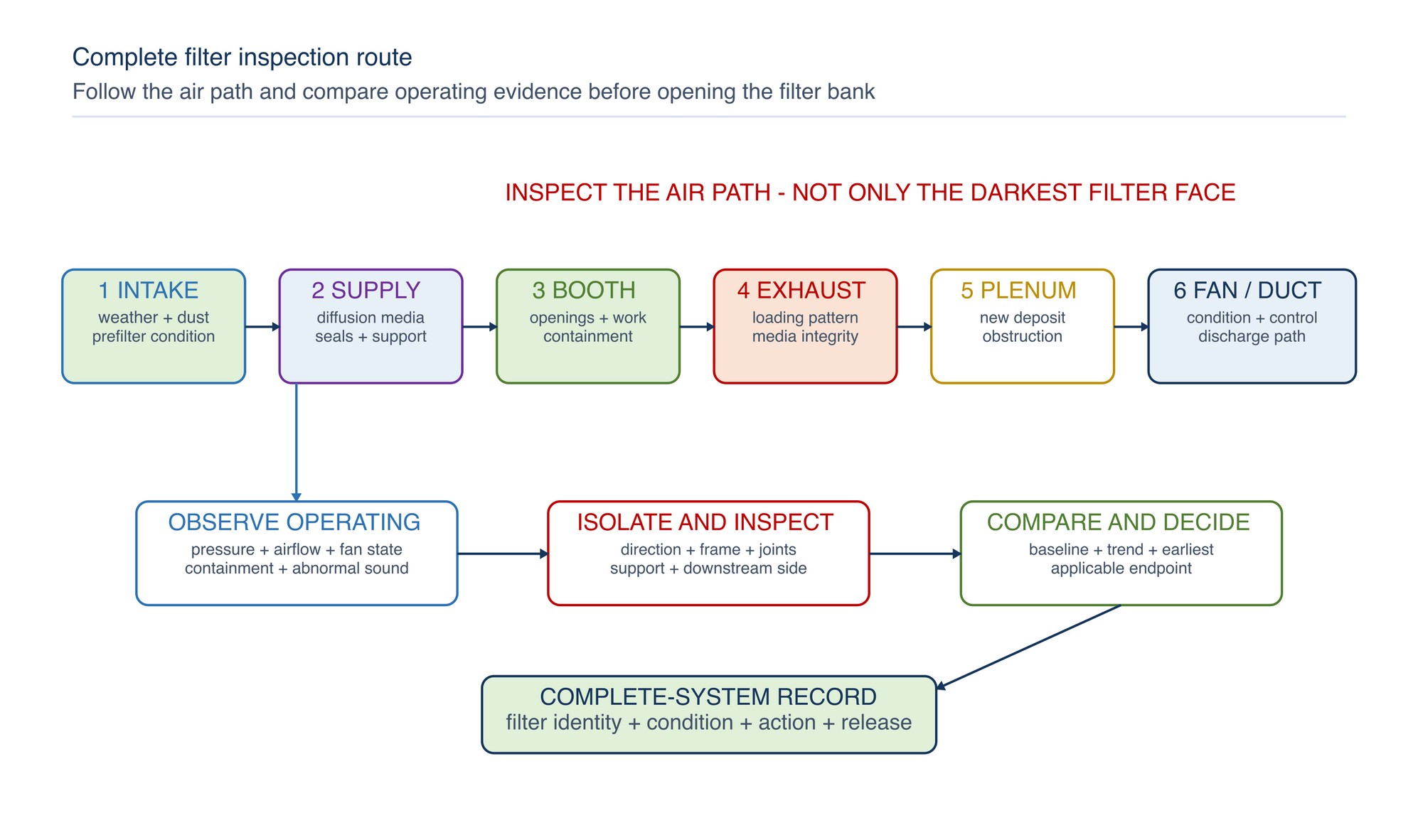
Inspect the complete filtration path
Inspection begins before touching the filter. Observe the booth while it is operating in its normal approved arrangement, then inspect the filter bank under the booth's isolation and access procedure. The useful inspection path follows the air:
- room or make-up-air intake;
- prefilter and supply-air stages;
- ceiling or diffusion media;
- booth work zone and openings;
- exhaust paint-arrestor face;
- supporting grid, frame and perimeter;
- downstream plenum, duct and fan approach; and
- pressure taps, gauge, alarms and control indication.
This route prevents a loaded exhaust filter from being blamed for a blocked intake, shut damper, dirty plenum, damaged fan or gauge fault. DOSH Malaysia treats local exhaust ventilation as a complete system of hood or enclosure, duct, air cleaner and fan, with regular inspection and maintenance of all components. [S171]
Use a repeatable visual inspection
Visual inspection is strongest when the same zones, lighting and observation order are used each time. Inspect with the bank operating where observation is safe and permitted; complete hands-on checks only after the required shutdown, run-on, clearance and isolation sequence.
| Inspection zone | Acceptable condition | Warning signs | Immediate direction |
|---|---|---|---|
| Media face | Continuous coverage, stable shape and broadly explainable loading | Tears, holes, cuts, wet pooling, heavy crust, detached layers or exposed openings | Stop spraying for damage, exposed area or unstable media |
| Loading pattern | Even or consistent with the verified spray path and booth geometry | One saturated zone, clean streaks, edge-only loading or repeated high/low bands | Check airflow distribution, work position, spray aim and frame seal |
| Frame and perimeter | Media seated continuously with no visible gap | Missing clips, open corners, warped frame, compressed-off gasket or loose roll edge | Restore the mechanical seal before operation |
| Support | Grid or retainer supports the media without crushing it | Sag, flutter, bowing, pulled pleats or media moving toward the fan | Replace damaged media and correct support or direction |
| Upstream area | No excessive loose deposit or obstruction | Overspray mound, blocked open area, loose masking, paper or parts | Remove the obstruction by the approved cleaning method |
| Downstream plenum | Clean enough to identify new deposits; no wet paint trail | Fresh paint dots, streaks, puddles or growing deposit | Investigate bypass, damage or insufficient capture before restart |
| Pressure system | Gauge connected, legible and responsive | Broken tube, paint-blocked port, fluid loss, stuck pointer, abnormal zero | Restore valid measurement; do not infer condition from a faulty gauge |
| Fire and access controls | Required protection and access remain serviceable | Covered sprinkler, obstructed access, accumulated combustible residue or ignition source | Stop and restore the applicable safety control |
Use photographs from fixed positions where practical. A close-up proves media condition; a full-bank photograph shows distribution. Record the booth state, filter stage, airflow direction and date so photographs remain meaningful.
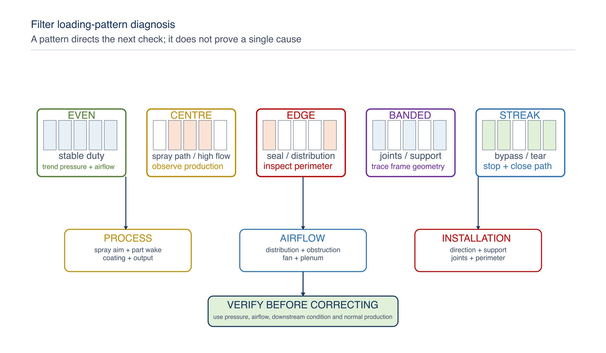
Read loading patterns as system evidence
The shape of the deposit often reveals more than its colour. Compare the current pattern with earlier photographs and the physical layout of parts, guns, openings and plenums.
| Pattern | Likely contributors | Verification check | Corrective direction |
|---|---|---|---|
| Broad, progressive loading | Normal accumulation under stable duty and production output | Comparable pressure, airflow condition | Continue to the established endpoint |
| Heavy centre, light edges | Concentrated spray path, part wake or central high flow | Observe normal work position and airflow distribution | Improve application path or distribution; do not patch the centre only unless the system method permits zoning |
| Heavy edges, light centre | Perimeter leakage path, centre obstruction or plenum distribution issue | Inspect seal, support, frame and downstream geometry | Restore seal and distribution before changing media grade |
| Alternating vertical or horizontal bands | Open joints, roll expansion error, support bars or local velocity variation | Trace bands to frame joints and pleat geometry | Reinstall with correct expansion, overlap and support |
| Clean streak through dirty bank | Gap, torn media, folded edge or bypass channel | Inspect both sides and downstream deposit trail | Stop spraying and close the bypass path |
| Wet pools or run-off | Excess local wet load, low airflow, unsuitable orientation or insufficient capacity | Check spray rate, transfer, airflow and media duty | Correct process and evaluate suitable holding construction |
| Sudden full-face skin | Fine/tacky mist, moisture, process change or dense first stage | Confirm coating, atomisation, ambient and filter identity | Correct the cause and reassess stage arrangement |
| Downstream paint with modest face loading | Bypass, reverse installation, damage or unsuitable capture duty | Check direction, seals, backing and fine-stage condition | Restore installation or select the declared capture duty |
Uneven loading is a symptom, not a diagnosis. Replacing only the darkest section can move airflow toward the new low-resistance area and make distribution less stable. Zone replacement is appropriate only where the booth and filter arrangement are designed and controlled for it.
Monitor differential pressure correctly
Differential pressure is the resistance between two defined points. Across a filter bank, it normally increases as deposited material restricts the available flow paths. The reading is valuable only when the pressure taps, gauge, fan/control state, doors, dampers and airflow condition are comparable.
Before relying on a reading:
- confirm both pressure tubes are connected to the intended upstream and downstream points;
- inspect tubes for splits, kinks, condensation, paint blockage and reversed connections;
- check the instrument zero under its specified condition;
- confirm the gauge range and units are appropriate and legible;
- identify whether the reading covers one stage, several stages or the whole booth; and
- record fan speed or control state, door position and production condition.
| What pressure alone cannot prove | Pressure behaviour | Possible meaning | Next check |
|---|---|---|---|
| Normal accumulation | Gradual rise from a stable clean baseline | That airflow and capture remain acceptable | Airflow/containment and physical condition |
| Rapid rise | Heavy loading, surface blinding, moisture, wrong media, compressed media or downstream restriction | Which cause is responsible | Loading pattern, coating/process change and stage-by-stage condition |
| Unusually low reading | Clean bank, low airflow, torn media, open bypass, disconnected gauge or blocked tap | That the bank is healthy | Gauge response, airflow and downstream deposit |
| Reading falls without a filter change | Flow reduction, media rupture, collapse, bypass opening or gauge fault | That resistance has improved | Fan state, physical integrity and gauge system |
| Oscillating reading | Fluttering media, unstable fan/control, opening doors or turbulent pressure taps location | The time-averaged filter condition | Media support, operating sequence and instrument location |
| New clean bank reads higher than the previous clean baseline | Different media, excess layers, wrong direction, compression, obstruction or changed airflow | That the new media is defective | Identity, installation, effective area and fan state |
Never convert a supplier's final-resistance value into a universal booth limit. The safe replacement point may be earlier because airflow, containment, motor load, physical stability, fire control or downstream cleanliness reaches its limit first. Refer to the product label, Technical Data Sheet, or MKTECH representative.
Link pressure to airflow and containment
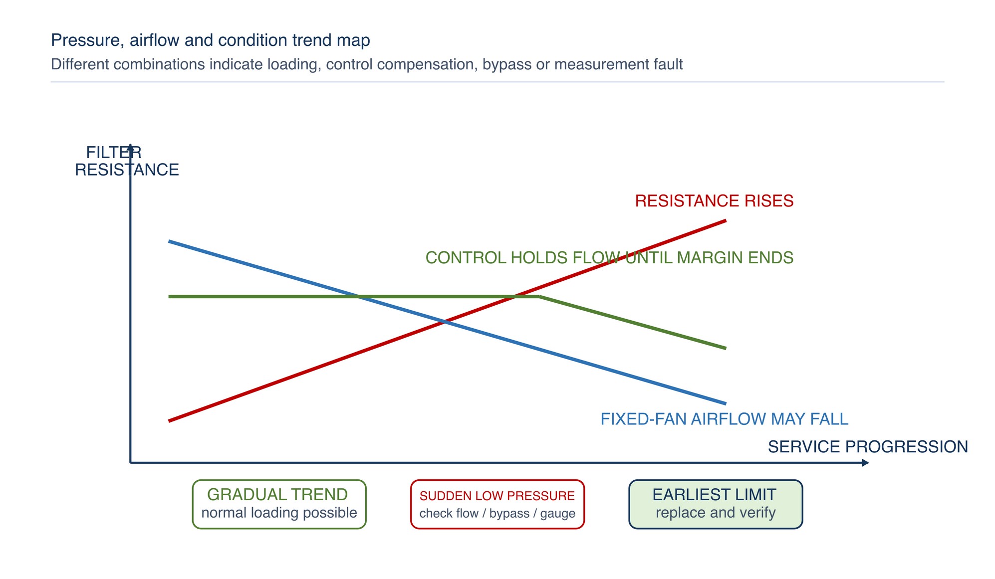
Pressure drop and airflow are related through the complete fan system, but one is not a substitute for the other. With a fixed-speed fan, increasing system resistance commonly reduces flow. With a controlled-flow system, the drive may increase fan effort to hold flow until it reaches a control or motor limit. A stable pressure reading can therefore accompany different airflow conditions if the control state changes. [S171; S194; S195]
Use one or more verified operational indicators appropriate to the booth:
- face or cross-sectional airflow measurement under the approved method;
- fixed-position velocity checks used for trending;
- airflow indicator, alarm or interlock status;
- smoke or visual containment test performed by a competent person with suitable test material;
- booth pressure relationship to the surrounding area;
- fan speed, drive output or motor condition; and
- overspray behaviour at openings and workpiece position.
| Combined observation | Interpretation | Action |
|---|---|---|
| Pressure rises; airflow falls | Loaded resistance is consuming fan capability | Replace at the established endpoint and check for other restrictions |
| Pressure rises; airflow remains stable; fan effort rises | Control is compensating for loading | Monitor available control/motor margin and change at the earliest limit |
| Pressure is low; airflow is low | Fan, damper, intake or gauge problem is possible | Inspect the complete system before blaming the exhaust filter |
| Pressure is low; airflow appears high; downstream paint increases | Bypass, torn media or insufficient capture may be present | Stop spraying and inspect seals, integrity and stage duty |
| Pressure is normal; containment is poor | Distribution, cross-draft, openings or work position may be defeating capture | Correct booth boundary and airflow distribution |
| Pressure and airflow are normal; finish dust increases | Intake leakage, ceiling-filter damage or housekeeping may be responsible | Inspect clean-air stages and booth surfaces |
DOSH guidance uses baseline testing for comparison and calls for investigation where reduced flow or malfunction is indicated. Keep the site's statutory inspection and examination programme separate from routine operator checks, while making the two records support each other. [S171]
Recognise bypass, collapse and breakthrough
Bypass
Bypass is air passing around rather than through the intended media. It follows gaps at the perimeter, open joints, damaged gaskets, missing clips, poor roll overlap, unsealed frame connections or holes. Because the bypass path has lower resistance, it can remain deceptively clean while a downstream streak accumulates.
Typical indicators are:
- clean line or corner beside a loaded face;
- media lifting or fluttering at an edge;
- pressure lower than the established condition would suggest;
- paint trail on the clean side aligned with a joint; and
- local downstream deposit despite apparently suitable media.
Correct bypass mechanically. A finer filter cannot compensate for an open seal. Camfil's installation guidance for filter frames uses gasket compression and sealing between frame joints to prevent air bypass; the same transferable principle applies to a paint-booth bank while the booth and selected filter instructions govern the actual hardware. [S196]
Collapse
Collapse is loss of the media's intended shape or support under airflow, deposit weight, moisture or incorrect installation. It includes sagging, bowing, pleats pulling together, a pad being drawn through the grid, a pocket folding over, or a roll detaching from its anchorage.
Common contributors include reverse direction, insufficient support, excessive span, over-expansion or under-expansion, saturated deposit, media incompatible with the duty, abnormal pressure, damaged frame or missing retainers. Collapse can create both high local resistance and open bypass paths.
Stop spraying when the bank cannot retain its intended geometry. Replace the damaged section or bank, restore support and investigate the cause before restart.
Breakthrough
Breakthrough is paint or particulate appearing downstream of the installed filter system. It may be genuine penetration through intact media, but it can also result from bypass, tearing, poor joints, reverse installation, overloaded media, displaced backing or an unsuitable first/final-stage combination.
Confirm the route before selecting a finer grade:
- identify whether the deposit is wet paint, dry residue, rust, old contamination or other dust;
- trace its position back to the filter face, joints and frame;
- inspect direction, backing and mechanical condition;
- confirm the coating, atomisation and spray rate have not changed;
- check the downstream stage and pressure/airflow trend; and
- clean a defined downstream observation area so recurrence can be verified.
Set a condition-based replacement point
Replacement timing should be predictable but not arbitrary. A calendar schedule supports planning and inspection; it does not override an earlier physical or operational limit.
Replace at the earliest applicable endpoint:
- Declared filter endpoint: the product's stated final resistance, loading or service condition.
- Booth airflow endpoint: required airflow, containment or control range can no longer be maintained.
- Physical endpoint: tear, hole, sag, collapse, loose backing, run-off, detachment or damaged seal.
- Downstream endpoint: unacceptable breakthrough, deposit or protection loss.
- Fire/chemical endpoint: residue compatibility, heat, smoke, odour, curing or housekeeping condition requires removal.
- Process-quality endpoint: verified filtration condition is causing dust, dry spray, turbulence or finish defects.
- Maintenance endpoint: the planned stoppage is the safe opportunity to replace a bank that would not reliably complete the next production period.
| Replacement basis | Strength | Limitation | Best use |
|---|---|---|---|
| Differential-pressure endpoint | Primary condition indicator; direct trend of installed resistance | Depends on valid gauge and comparable airflow/control state | where correct pressure points exist |
| Airflow or containment endpoint | Confirms the booth remains effective as loading increases; directly relates to booth function | Requires a reliable measurement or indicator method | |
| Visual/physical endpoint | Detects damage, collapse, bypass and run-off | Appearance alone does not quantify remaining capacity | Mandatory inspection alongside pressure and airflow |
| Production-throughput trend | Supports stock and labour planning | Changes in coating, part or spray technique can invalidate comparison | Forecasting under stable production families |
| Calendar interval | Simple scheduling | Can replace too early or too late when duty changes | Maximum inspection/service prompt, not the only change trigger |
| Downstream-cleanliness endpoint | Reveals protection failure | May detect failure after contamination has occurred | Secondary confirmation and post-change verification |
For an exact replacement value or interval, Refer to the product label, Technical Data Sheet, or MKTECH representative.
Plan the change safely
Loaded filters can contain wet coating, solvent, reactive hardener and combustible residue. Plan the change around the coating SDS, chemical assessment, booth procedure, fire controls and waste route.
Before starting:
- stop spraying and complete the specified ventilation run-on or clearance period;
- isolate equipment and energy sources under the site procedure;
- confirm that the filter area is safe to enter and that required fire protection remains available;
- identify the coating residues and select the specified PPE and handling controls;
- prepare compatible, labelled waste containers close enough to prevent uncontrolled carrying;
- protect the clean side, booth floor and nearby components from released deposits;
- prepare the correct replacement identity, quantity, direction and support hardware; and
- prohibit hot work, ignition sources and compressed-air blow-off of paint deposits.
Do not shake, tear or drag loaded media across clean surfaces. Do not cut into a wet or heavily loaded pocket unless the approved method specifically requires it. Do not stack warm, wet or actively curing filters in an enclosed combustible pile.
Remove and clean in a controlled sequence
- Record the last comparable pressure, airflow/containment condition and observed loading pattern.
- Photograph the bank before removal if failure pattern or service life is being investigated.
- Remove media in manageable sections, supporting its weight and keeping the loaded face controlled.
- Place each section directly into the prepared container; segregate incompatible residues.
- Inspect the exposed frame, clips, grids, channels, gaskets and downstream side.
- Remove accessible loose residue by the booth's approved non-sparking, low-dispersion method.
- Check pressure taps and tubing without pushing contamination into the system.
- Record damage that needs repair before new media is installed.
Replacing media over a dirty, warped or unsealed frame preserves the failure. Frame cleaning is complete only when the seating surface can make a continuous seal and the downstream side is suitable for detecting new breakthrough.
Install in the correct direction
Filter media can be directional. Direction may be identified by an airflow arrow, upstream/downstream label, colour, backing, graduated density, pocket orientation, pleat geometry or product instructions. Appearance is not a reliable substitute for declared installation information.
Use this installation sequence:
- verify filter identity against the work order and installed location;
- identify airflow direction and the declared spray or dust side;
- inspect the replacement for moisture, crushing, tears, delamination or transport damage;
- clean and repair the seating frame before placing media;
- fit the media without compressing its designed depth or distorting pleats and pockets;
- close every joint, overlap and perimeter in the specified sequence;
- engage all clips, retainers, grids and anchors so deposit weight and airflow cannot displace the media;
- inspect both upstream and downstream sides where accessible; and
- confirm that no frame opening or unused area is exposed.
Roll and accordion media must be expanded or overlapped as specified. Under-expansion can reduce internal storage and leave open joints; over-expansion can flatten geometry and change resistance. Pocket and panel filters must be seated against the correct gasket face and supported in the intended airflow direction. Refer to the product label, Technical Data Sheet, or MKTECH representative.
Verify frame sealing and support
A sealed bank directs air through the media. Use a systematic perimeter-to-centre check:
- Perimeter: continuous contact with no visible daylight, folded edge or broken gasket.
- Corners: clips engaged and media not pulled away by tension.
- Joints: specified overlap, compression or sealing strip is continuous.
- Centre: no missing panel, crushed section or unsupported span.
- Retainers: installed without cutting, puncturing or excessively compressing media.
- Frame: square enough to seat the filter; no corrosion, dried paint ridge or damage holding an edge open.
- Downstream: no loose piece can be drawn into the fan or duct.
Where several frames form a bank, seal between the frames and between the bank and surrounding plenum as required. A perfect media-to-frame seal cannot correct leakage around the frame assembly itself. [S196]
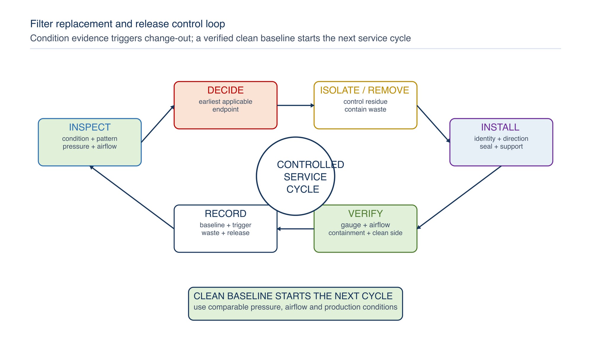
Establish the clean-bank baseline and release
The first controlled operating condition after replacement becomes the reference for later trending. Record it only after the bank has passed physical checks.
Release sequence:
- account for tools, offcuts and removed media;
- close access panels and restore guards, fire protection, pressure tubing and interlocks;
- remove isolation under the authorised procedure and start ventilation without spraying;
- observe the bank for flutter, movement, abnormal noise or pulling at joints;
- check the gauge zero/response and record the clean differential pressure;
- verify airflow, containment and booth pressure by the established method;
- inspect the downstream observation area and booth openings;
- conduct the authorised production check using normal coating and operating conditions; and
- record filter identity, installation date, baseline and release decision.
Stop and correct the installation if the clean reading, airflow or containment differs materially from the established condition, or if any gap, movement, unusual odour, smoke, heat or downstream deposit is observed.
Keep useful inspection and replacement records
A concise record should support the next operator, maintenance planner, environmental coordinator and purchaser. It should explain what changed and why without relying on memory.
| Record field | What to enter | Why it matters |
|---|---|---|
| Booth and filter location | Booth ID, supply/exhaust stage and bank/zone | Links the record to the correct pressure points and media |
| Filter identity | Manufacturer, product reference, format, size and batch where available | Supports traceability and repeat purchase |
| Installation details | Date, direction, quantity, expansion/overlap and sealing/support condition | Helps diagnose early failure or bypass |
| Clean baseline | Differential pressure, airflow/containment indicator and fan/control state | Establishes a comparable starting point |
| Inspection trend | Dates, readings, loading pattern, damage and downstream condition | Shows how the bank moved toward the endpoint |
| Production context | Coating family, major process changes and relevant production basis | Prevents false service-life comparisons |
| Change trigger | Pressure, airflow, physical, breakthrough, safety, quality or planned-maintenance endpoint | Makes replacement decisions auditable |
| Used-filter handling | Residue identity, classification, quantity, container and storage location | Supports safe segregation and Malaysian waste control |
| Transfer/disposal | Date, authorised route and required consignment or inventory reference | Completes traceability to the receiving route |
| Release result | Clean reading, airflow/containment check, downstream check and responsible person | Confirms the new bank returned to service correctly |
Use trends to forecast stock, not to create an unqualified guarantee. Service life can change with coating solids, spray rate, transfer efficiency, part geometry, operator technique, ambient dust, humidity, airflow and media construction. [S178; S195]
Control disposal records in Malaysia
Used-filter classification follows the captured coating residue and the generating process. The waste generator identifies the applicable category using process and chemical information; the clean carrier material alone does not determine the route.
DOE Malaysia requires scheduled waste, where applicable, to follow prescribed storage, labelling, inventory, transport and authorised-receiving controls. [S188; S189]
Use the following record chain:
- link the removed filter to the coating, hardener, thinner and process period;
- determine the applicable waste classification from the actual residue and generating process;
- segregate incompatible waste streams;
- record the date, quantity, container identity and designated storage location;
- maintain the required current inventory and labels;
- use authorised transport and receiving arrangements where required; and
- retain the applicable inventory and movement records for the prescribed period.
Do not assign one universal waste code to all paint-booth filters. DOE Malaysia states that the waste producer is responsible for classification because it knows the raw materials and generating process. [S189]
Troubleshoot inspection and replacement problems
| Symptom | Likely causes | Verify first | Corrective direction |
|---|---|---|---|
| Filters block much sooner than expected | Higher spray load, finer/tackier mist, reduced area, moisture, wrong media or compressed installation | Process change, face pattern, identity and airflow | Correct application/system cause and select capacity within the booth duty |
| New filter gives high pressure immediately | Wrong product, excess layers, reverse direction, over-compression, obstruction or changed flow | Identity, installation, gauge and fan state | Reinstall correctly or use the declared compatible configuration |
| Pressure stays low as filters load | Gauge fault, bypass, tear, low airflow or pressure taps across the wrong points | Gauge response, seals, media integrity and airflow | Restore valid measurement and sealed bank |
| Filter collapses | Wrong direction, missing support, excessive span, wet load, abnormal resistance or unsuitable construction | Support grid, frame, media duty and pressure trend | Replace damaged media and correct the cause before restart |
| Edge pulls away | Poor anchoring, incorrect roll tension/expansion, warped frame or deposit weight | Clips, perimeter and installation method | Repair frame and reinstall with continuous restraint |
| Downstream paint appears after change | Open joint, reversed backing, torn media, wrong stage or old downstream residue | Clean a defined area; inspect direction and seals | Correct installation and confirm capture duty |
| One zone repeatedly saturates | Local spray aim, part wake, uneven airflow, blocked plenum or inactive bank area | Observe normal production and perform distribution checks | Correct process/distribution; assess designed zoning only if appropriate |
| Finish dust rises after exhaust change | Intake leakage, disturbed booth dirt, damaged ceiling media or turbulence | Intake stages, housekeeping and airflow balance | Restore clean-air path and booth condition |
| Fan effort or noise increases | Loaded resistance, obstruction, control compensation or mechanical issue | Pressure profile, fan/control state and full system | Replace at endpoint and service the system cause |
| Filters are being changed too often without evidence | Calendar habit, inconsistent endpoint or poor records | Compare pressure, airflow, condition and production basis | Adopt condition-based records and a defined earliest endpoint |
Repeated failure after correct installation is a system signal. Re-run the Chapter 034 selection method using the current coating, overspray volume, booth airflow, effective area, pressure allowance, capture duty and disposal route.
Concise safety reminders
- Keep ventilation, interlocks, grounding and fire protection in their designed operating state.
- Stop spraying for tears, open gaps, collapse, run-off, breakthrough, loss of containment, heat, smoke or smouldering odour.
- Do not use gauge pressure as the only proof of airflow or capture.
- Never increase fan limits to conceal a loaded or unsuitable filter.
- Do not mix filter residues from coatings that can react or self-heat together.
- Prevent ignition sources and uncontrolled compressed-air cleaning in paint and filter areas.
- Wear the PPE and use the handling method specified by the coating assessment and booth procedure.
- Place removed filters directly into the correct compatible container; do not leave them beside the booth.
- Treat used filters according to the captured residue and applicable Malaysian waste requirements.
- Verify direction, sealing, support, pressure indication, airflow and downstream condition before production release.
Paint-Booth Troubleshooting
Paint-Booth Troubleshooting appears on the following page of the printed handbook (page 298), outside this chapter extract.