
Paint-shop supervisors, booth operators, maintenance teams, production engineers, QA/QC personnel, safety and environmental personnel and technical sales personnel
A practical, symptom-led method for diagnosing overspray escape, reduced airflow, dust contamination, uneven finish, excessive filter consumption, fan overload, filter bypass, odour, premature blockage and poor capture.
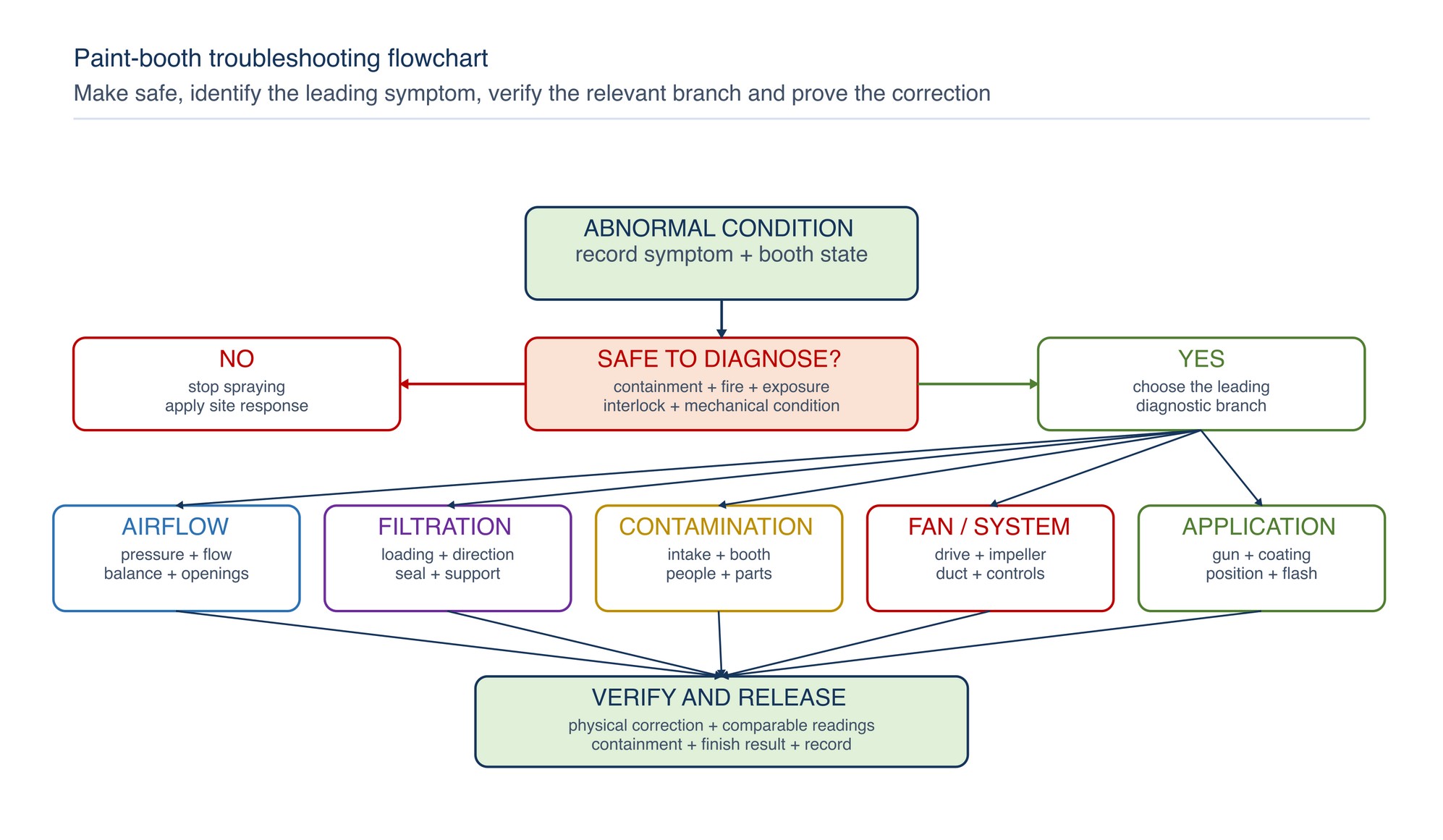
Treat the booth as one connected air-handling and coating system. Confirm safety and containment first, then separate airflow, filtration, contamination, fan and application causes before changing a setting or component.
Stop spraying when mist is visibly moving into occupied space or depositing outside the controlled area. Keep mechanical ventilation operating for the required post-spray clearance period unless the emergency procedure or responsible safety authority directs otherwise. Do not enter or open hazardous areas merely to investigate a fault. Isolation, atmospheric control, personal protective equipment and access arrangements follow the coating Safety Data Sheet, booth procedure and site risk controls. Do not defeat overload protection, bypass an interlock or increase speed merely to recover a lost airflow reading. [S153; S160; S172; S175; S177]
Chapter objectives
After this chapter, the reader should be able to:
- identify conditions that require spraying to stop before diagnosis continues;
- use a symptom-first troubleshooting flowchart;
- distinguish low-flow, poor-distribution and poor-balance faults;
- trace filter bypass separately from media penetration or mechanical damage;
- investigate dust and finish defects without assuming the filter is responsible;
- diagnose high filter usage and premature blockage from production and system evidence;
- recognise fan overload, noise and vibration as system faults requiring authorised maintenance;
- respond appropriately to odour without treating a particulate filter as a vapour filter;
- verify corrective action under a comparable operating condition; and
- record the cause, action and result so repeated failures can be prevented.
Make the booth safe before troubleshooting
Stop spraying and follow the site's emergency or isolation procedure when any of the following is observed:
- visible overspray or vapour is escaping into occupied work areas;
- smoke, fire, unusual heat, sparking or burning odour is present;
- a ventilation, fire-protection, access-door or spray-permissive interlock has operated;
- the exhaust or supply fan has stopped, stalled or developed severe noise or vibration;
- a filter has collapsed, detached or opened a direct bypass path;
- a significant liquid spill, wet paint accumulation or combustible deposit is present; or
- personnel report acute irritation, dizziness, breathing difficulty or other exposure symptoms.
Keep mechanical ventilation operating for the required post-spray clearance period unless the emergency procedure or responsible safety authority directs otherwise. Do not enter or open hazardous areas merely to investigate a fault. Isolation, atmospheric control, personal protective equipment and access arrangements follow the coating Safety Data Sheet, booth procedure and site risk controls. [S153; S160; S172; S175; S177]
Start with the symptom, then split the system
A paint-booth symptom rarely proves a single cause. Overspray at the opening may come from low exhaust flow, excessive make-up air, cross-draught, poor work position or spray aimed outside the capture path. Dust on a part may enter through intake leakage, fall from booth surfaces, come from clothing or be created by the coating process. A loaded filter may be the cause of reduced flow, but it may also be the result of excessive overspray. Effective troubleshooting therefore follows evidence through the complete intake\u2013booth\u2013filter\u2013duct\u2013fan path. [S171; S172; S178]
Record what changed before touching the booth. Identify the affected product, coating, shift, operator, spray gun, filter stage and time. Note whether the symptom appeared suddenly, developed gradually or followed maintenance, a coating change, a production increase or unusual weather.
Use five diagnostic branches:
- Airflow and pressure — restriction, insufficient make-up air, open doors, cross-draught, damper position or changed control state.
- Filtration and sealing — loaded media, wrong direction, poor expansion, damaged support, frame gap, breakthrough or unsuitable duty.
- Contamination and housekeeping — dirty intake, booth deposits, clothing, compressed air, sanding dust, part contamination or disturbed floor material.
- Fan and mechanical condition — belt, bearing, impeller deposits, rotation, obstruction, electrical load, vibration or system effect.
- Coating and application — viscosity, temperature, atomisation, spray distance, overlap, gun condition, flash-off, part geometry or excessive overspray generation.
Overspray escaping the booth
Escaping overspray is a containment failure. Stop spraying when mist is visibly moving into occupied space or depositing outside the controlled area. Do not compensate by moving the operator, opening another door or increasing fan speed without understanding booth balance.
| Observation | Likely contributors | Verification | Corrective direction |
|---|---|---|---|
| Mist rolls out across the full opening | Low exhaust flow, excessive supply, restricted exhaust bank or open boundary | Compare airflow, pressure and fan/control state with the accepted operating baseline | Restore the verified airflow path and booth balance |
| Escape occurs at one edge | Cross-draught, local supply jet, open door, blocked section or poor work position | Map direction at the opening and inspect local filter loading | Remove the disturbance or correct distribution |
| Escape follows the spray gun movement | Gun aimed outside capture path, excessive distance, rebound or poor part positioning | Observe the normal application technique within the approved process from a safe position | Reposition work and refine technique |
| Escape begins after filter loading | Rising resistance and falling flow | Review pressure and airflow trend with physical filter condition | Replace at the established endpoint and verify the clean-bank baseline |
| Escape begins after filter change | Wrong medium, excess layers, reverse direction, compression, gap or control change | Confirm identity, direction, fit, support and fan state | Reinstall correctly or restore the selected system configuration |
DOSH guidance treats enclosure performance, capture and the complete exhaust system as connected. A useful correction must restore both containment and the operating indications used for the booth baseline. [S171; S172]
Reduced airflow and poor capture efficiency
Reduced airflow is a measured or observable loss of air movement. Poor capture is failure to collect mist and residue at the source. They often occur together, but not always: total airflow may be adequate while distribution, part location or a cross-draught defeats capture.
Check the air path in order:
- room and make-up-air openings;
- intake and ceiling-filter stages;
- booth openings, doors and temporary screens;
- workpiece position and blockage;
- exhaust filter bank and support;
- downstream plenum and duct;
- damper and control state; and
- fan, drive and discharge condition.
| Pressure/airflow pattern | Most useful interpretation | Next action |
|---|---|---|
| Pressure rising, airflow falling | Filter or downstream resistance is consuming available fan capability | Inspect each stage and remove the verified restriction |
| Pressure rising, airflow stable, fan effort rising | A control system may be compensating | Confirm motor/control margin and replacement endpoint through authorised maintenance |
| Pressure low, airflow low | Fan output, damper, supply restriction or measurement fault is likely | Verify fan/control state and measuring system |
| Pressure normal, capture poor | Distribution, cross-draught, work position or excessive mist generation may dominate | Check local air direction and application path |
| Pressure falls suddenly, downstream deposit rises | Rupture, bypass or media displacement is possible | Stop spraying and inspect integrity and sealing |
Use fixed, repeatable measurement positions and a comparable booth state. A handheld spot reading taken at a different location, door arrangement or fan mode may suggest a change that is not real. Exact operating values must match the installed booth and selected filter system. Refer to the product label, Technical Data Sheet, or MKTECH representative.
Dust on painted parts
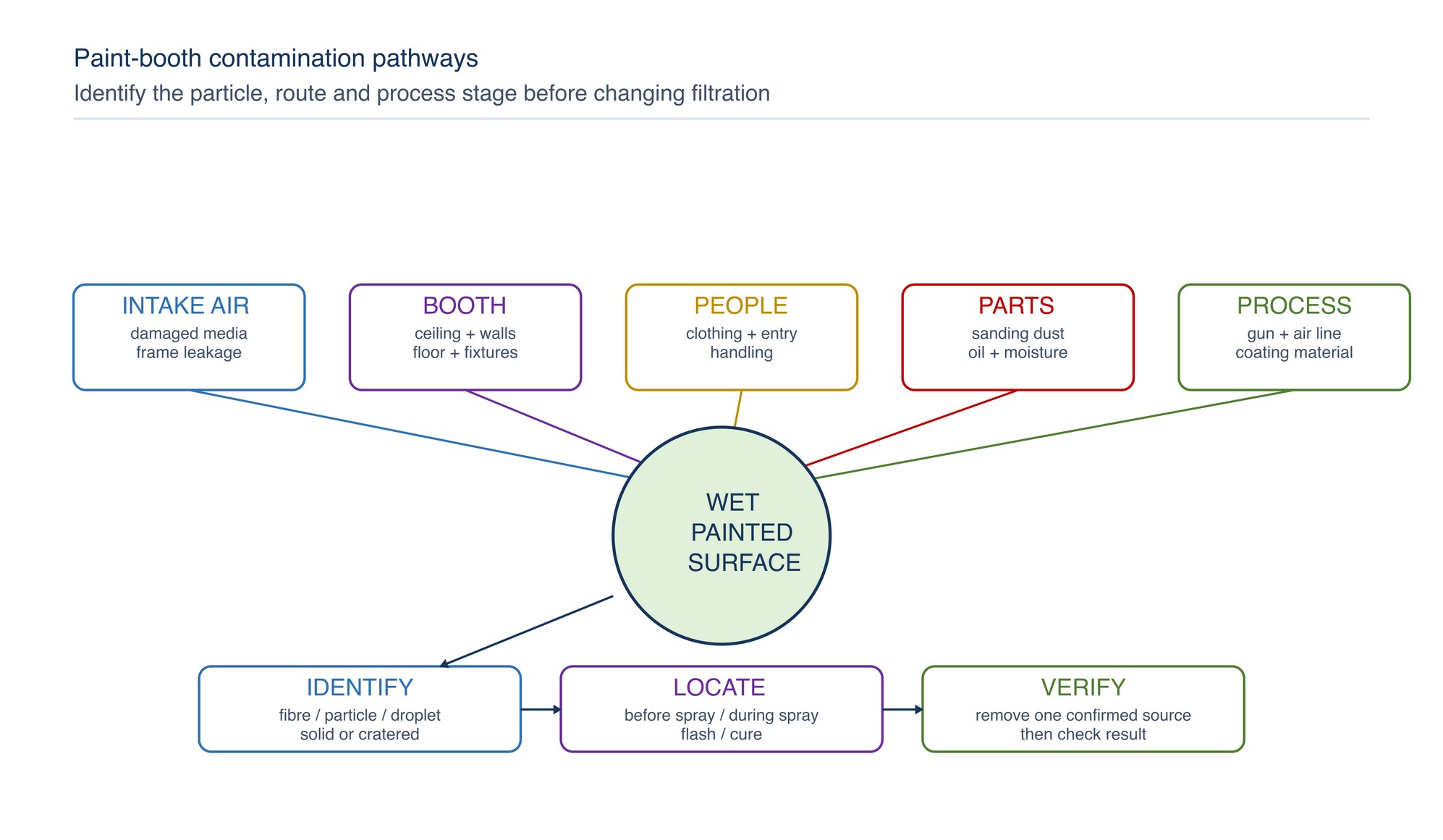
Dust contamination may reach the wet film before spraying, during application, during flash-off or while the coating cures.
First determine whether the particles are loose, embedded, fibrous, metallic, paint-like or cratered around a liquid contaminant.
| Evidence | Likely source | Verification | Corrective direction |
|---|---|---|---|
| Fibres match intake or ceiling media | Damaged media, poor support, reverse installation or disturbed surface | Compare particle appearance and inspect the clean-air stages | Correct installation and replace damaged media |
| Dust concentrated on upper faces | Falling deposit from ceiling, fixtures, clothing or poor cleaning discipline | Inspect overhead surfaces and observe entry/handling | Clean by the approved method and improve contamination discipline |
| Dirt increases near doors | Uncontrolled entry, pressure imbalance or cross-draught | Compare defect location with opening behaviour | Restore booth boundary and entry control |
| Metallic or abrasive particles | Inadequate part cleaning or adjacent grinding/sanding | Examine preparation and transfer route | Separate dirty work and clean parts before coating |
| Defect appears after flash-off | Contaminated flash area, disturbed floor deposit or airflow reversal sequence | Track part movement and airflow state after spraying | Control the post-spray environment and clearance |
| Craters or fisheyes rather than solid particles | Oil, silicone, water, compressed-air contamination or substrate residue | Inspect air quality, cleaning materials and part-preparation history | Remove the verified contaminant source and requalify the process |
Do not increase intake-filter grade automatically. A finer filter cannot correct an open frame, dirty booth, contaminated part or unsuitable compressed air, and added resistance may reduce airflow if the fan system cannot support it.
Uneven finish
Uneven colour, gloss, texture or film build can arise from airflow, but application and coating variables remain equally important. Diagnose the spatial pattern.
- A repeated defect on the same booth side suggests airflow distribution, local temperature, supply jet or opening effects.
- A defect that follows the operator or gun suggests spray distance, angle, overlap, atomisation or gun condition.
- A defect tied to part geometry suggests shielding, rebound, edge build or difficult access.
- A defect that begins after a filter change suggests changed airflow distribution, media orientation, excess resistance or disturbed contamination.
- A defect that follows a coating batch or environmental change suggests viscosity, mixing, temperature, humidity, flash or cure conditions.
| Finish symptom | Booth-related checks | Process-related checks |
|---|---|---|
| Dry spray or roughness | Excess local air velocity, turbulent jet, long travel to exhaust | Gun distance, atomisation, solvent balance, coating temperature |
| Sags or heavy area | Low or uneven air movement, local dead zone | Film build, overlap, viscosity, gun output |
| Uneven metallic orientation | Cross-flow disturbance or inconsistent booth balance | Gun path, overlap, flash and material preparation |
| Mottling or patchiness | Local airflow or temperature variation | Application sequence, wetness and coating-specific technique |
| Craters/fisheyes | Air or surface contamination | Cleaning chemistry, oil, silicone, water and compressed air |
| Dull or variable gloss | Contamination, airflow or cure uniformity | Mix ratio, flash, film build, substrate and cure conditions |
Keep acceptance against the approved finish sample or job specification. When coating-specific values are required, refer to the coating Technical Data Sheet and Safety Data Sheet.
High filter usage and premature blockage
Short service life is an outcome, not a sufficient reason to fit a more open medium. Determine whether the filters are collecting an unusually high load, presenting insufficient effective area, blinding at the surface or being replaced before the true endpoint.
Common causes include:
- increased production hours, spray rate or coating solids;
- lower transfer efficiency, poor gun condition or excessive test spraying;
- work positioned too close to one filter zone;
- filter media compressed, under-expanded, layered incorrectly or installed backwards;
- moisture, tacky mist or incompatible residue closing the surface;
- one stage carrying load intended for a staged system;
- restricted intake or downstream path forcing an abnormal operating point;
- replacement triggered by appearance alone rather than combined condition evidence; and
- poor sealing that overloads a downstream stage.
Use a common basis such as accepted coated components or controlled spray hours when comparing service life. Record the coating family, production mix, filter identity, pressure/airflow trend, reason for removal and observed loading pattern. Do not claim improved life from a substitute until the complete system has been evaluated under comparable duty.
Fan overload, abnormal noise and vibration
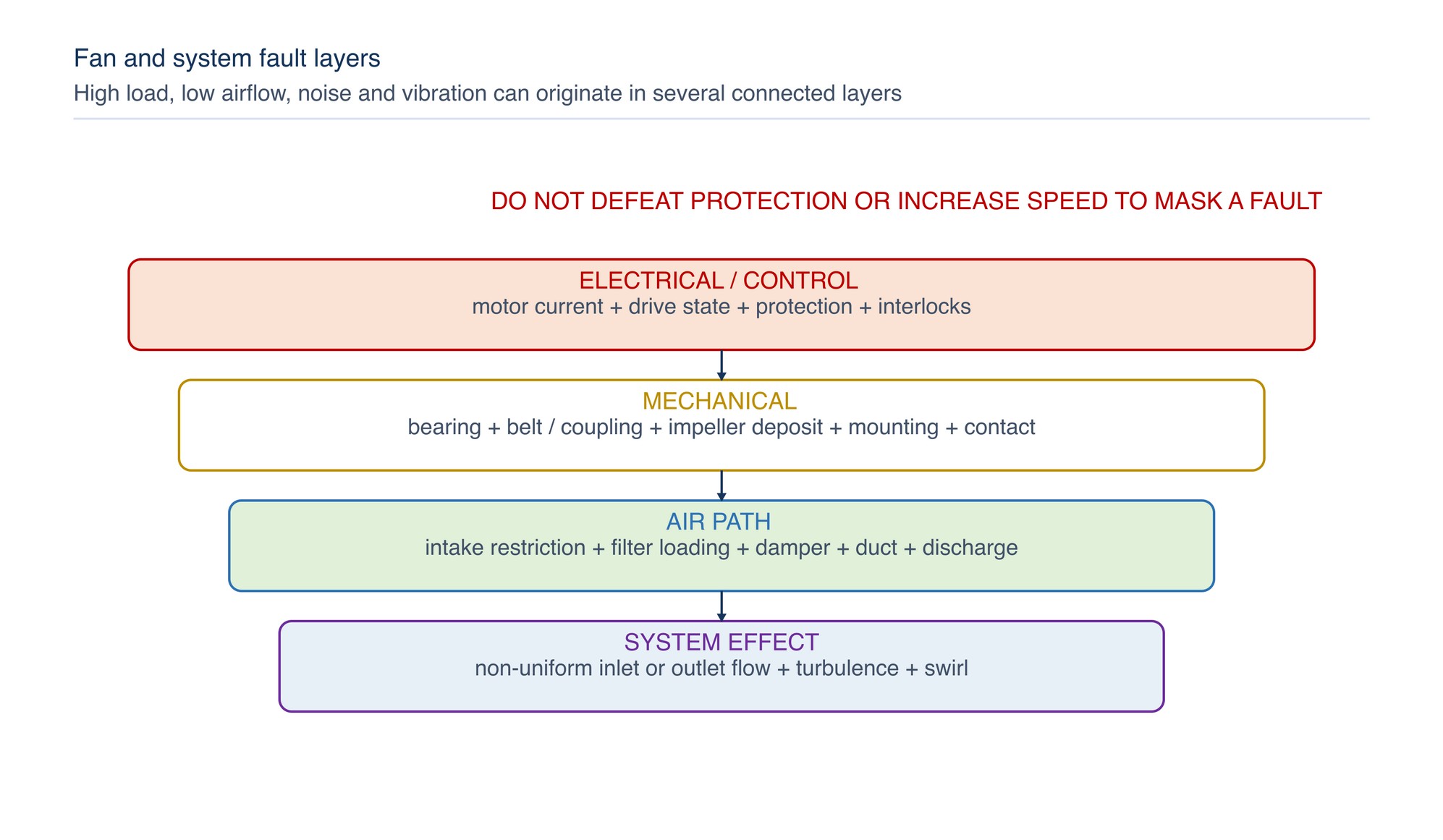
Fan overload may appear as high motor current, protection trips, overheating, reduced speed, control alarms or repeated starter operation. Noise and vibration may point to impeller deposit, imbalance, bearing condition, belt or coupling fault, loose mounting, contact, foreign material, flow instability or adverse inlet/outlet conditions. [S175; S179; S197]
| Symptom | Possible causes | Safe diagnostic direction |
|---|---|---|
| Motor current or drive load rises with filter loading | Control compensation, changed duty point or added resistance | Compare fan mode, airflow and pressure trend; use authorised electrical measurement |
| Fan trips after maintenance | Wrong rotation, damper state, belt tension, obstruction, wiring/control issue or changed filter resistance | Isolate and verify the maintenance scope before restart |
| Vibration builds gradually | Impeller deposit, bearing wear, loose mounting or imbalance | Stop within the site's vibration/escalation rule and inspect under isolation |
| Sudden impact or scraping noise | Foreign object, loose component or rotating-element contact | Stop immediately and isolate |
| Airflow is low despite high fan effort | Excess system resistance, system effect, blockage or fan degradation | Inspect complete intake, duct and discharge path |
| Pulsing or hunting | Unstable control, damper interaction, stalled flow or rapidly changing booth pressure | Review control signals and air-path stability with competent maintenance |
Do not defeat overload protection, bypass an interlock or increase speed merely to recover a lost airflow reading. The fan, motor, drive, duct and filters are selected as a system. Refer to the product label, Technical Data Sheet, or MKTECH representative.
Filter bypass and downstream paint
Bypass is flow around rather than through the intended filter area. It can occur at the perimeter, between panels, through an under-expanded roll, around a warped frame, at a missing clip or across a damaged gasket. Penetration is passage through the media; breakthrough may describe unacceptable downstream carry-over from penetration, overload, damage or bypass. These mechanisms need different corrections. [S178; S195; S196]
Trace a fresh downstream deposit upstream to its route:
- isolate the booth and inspect the deposit shape;
- look for a matching clean streak, open edge, joint or damaged zone on the filter face;
- confirm airflow direction and required backing or support;
- verify continuous frame contact and joint sealing;
- inspect for collapse, cut, puncture or paint-softened structure;
- confirm that the installed medium is intended for the coating and stage duty; and
- clean the affected downstream area by the approved method before release so new carry-over can be identified.
A higher-efficiency medium cannot correct an open bypass path. Exact direction, expansion, overlap, support and sealing details are product specific. Refer to the product label, Technical Data Sheet, or MKTECH representative.
Odour inside or around the booth
Odour can indicate poor containment, inadequate clearance, exhaust re-entry, a spill, residue accumulation, coating-process change or a problem with a dedicated vapour-control system. Odour intensity is not a reliable measure of chemical concentration or safety.
Most dry intake and overspray filters are particulate-control devices; they do not remove solvent vapours merely because they capture paint mist. [S178] If odour is unusual, strong, persistent or accompanied by symptoms, stop work and apply the site's chemical-exposure response.
Check:
- exhaust fan and spray-permissive status;
- containment at openings and doors;
- post-spray clearance and drying/flash mode;
- exhaust discharge relative to make-up-air and building intakes;
- spills, wet deposits, waste containers and contaminated filter storage;
- coating identity, mix, application rate and Safety Data Sheet;
- make-up-air path and adjacent work; and
- the condition and declared service endpoint of any dedicated vapour-treatment stage.
Do not add an improvised carbon layer or recirculate exhaust air as a quick odour remedy. Vapour control, fire protection and discharge arrangements require competent system review.
Diagnose the system with comparable evidence
The strongest fault record combines four evidence groups.
| Evidence group | Record | Why it matters |
|---|---|---|
| Symptom | Location, time, severity, photograph and affected product | Defines the problem without assuming the cause |
| Operating state | Booth mode, doors, fan/control indication, dampers and concurrent work | Makes readings comparable |
| Air and filter condition | Pressure, airflow/containment observation, filter identity, loading and seals | Separates restriction, distribution and bypass |
| Process context | Coating, gun, part, spray route, production load and recent changes | Tests whether the booth fault is actually generated by application |
Compare with an accepted clean-bank and normal-production baseline. Check the measuring instrument before concluding that the system changed. DOSH guidance supports periodic inspection and testing of the complete local exhaust system, with investigation and maintenance when performance deteriorates. [S171]
Correct one verified cause at a time
Changing several variables together may restore production but destroys the evidence needed to prevent recurrence.
Where safe and practical:
- identify the most likely verified cause;
- select a corrective action within the authorised operating method;
- restore the system to a known configuration;
- repeat the same observation or measurement;
- coat an appropriate confirmation piece where production quality must be proven; and
- record the result before introducing another change.
Possible corrections include replacing a condition-ended filter, reseating and sealing the bank, restoring the intended make-up-air path, removing an obstruction, cleaning a plenum, repairing a damaged support, correcting part position, servicing a spray gun or escalating fan/control work to competent maintenance.
Verify return to service
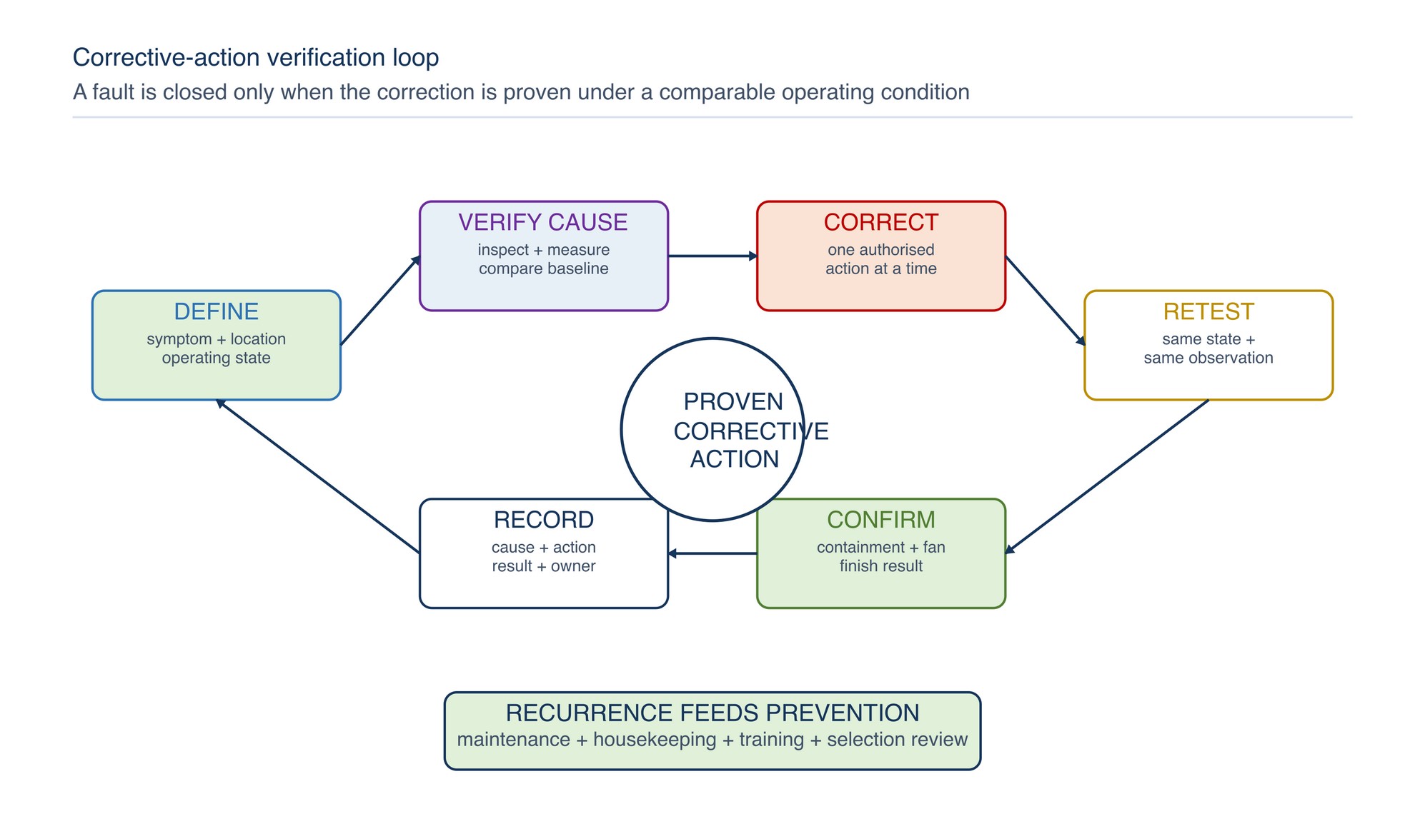
Before normal spraying resumes, confirm:
- the fault area is physically corrected and all temporary materials are removed;
- filter identity, direction, coverage, support and perimeter sealing are correct;
- pressure instruments and control indications respond normally;
- fans operate without abnormal heat, noise, vibration or alarm;
- airflow and containment match the accepted operating method;
- doors, access panels, dampers, guards and interlocks are restored;
- the booth and downstream area are clean enough to identify recurrence;
- a verification spray or first-off part meets the applicable finish criteria; and
- the action, verification result and responsible person are recorded.
Where an exact pressure, airflow, electrical, clearance or product limit is required, Refer to the product label, Technical Data Sheet, or MKTECH representative.
Quick troubleshooting matrix
| Symptom | Check first | Common root causes | Avoid |
|---|---|---|---|
| Overspray escaping | Fan/interlock, containment and opening airflow | Loaded bank, imbalance, cross-draught, poor work position, excessive mist | Continuing production or opening more doors |
| Reduced airflow | Complete intake-to-discharge path | Loaded stages, obstruction, fan/damper fault, restricted make-up air | Increasing speed without system review |
| Dust on parts | Particle type and point of appearance | Intake leak, booth deposits, clothing, part or compressed-air contamination | Assuming finer media is the only answer |
| Uneven finish | Spatial pattern and recent changes | Distribution, gun path, viscosity, temperature, part geometry | Changing booth and coating variables together |
| High filter usage | Production load and removal trigger | Excess overspray, compressed media, moisture, poor staging, early change | Comparing by calendar days alone |
| Fan overload | Alarm, current/load trend and mechanical condition | Compensation, blockage, deposit, imbalance, bearing or control fault | Defeating protection or repeated resets |
| Filter bypass | Perimeter, joints, support and downstream trail | Gap, reverse direction, damage, under-expansion, warped frame | Selecting finer media before sealing |
| Odour | Ventilation, containment, clearance and spill/residue | Exhaust re-entry, process change, spill, wet waste, vapour-control issue | Treating particulate media as vapour control |
| Premature blockage | Loading pattern and coating/process change | High solids load, tacky mist, local spray path, insufficient area | Substituting media without system-fit review |
| Poor capture | Local air direction and work position | Low flow, cross-draught, obstruction, distribution or excessive generation | Relying on pressure alone |
Prevent repeated faults
A stable booth is maintained through short, regular checks rather than emergency changes alone:
- inspect visible filter condition, sealing and loading distribution;
- trend pressure, airflow indication and fan/control state together;
- keep booth surfaces, plenums and access areas clean by the approved method;
- maintain spray guns and compressed-air quality;
- protect clean parts and control dirty work around booth entrances;
- review filter consumption against accepted production, not calendar time only;
- examine repeated defect location on a simple booth map;
- investigate sudden changes after maintenance or material substitution; and
- feed recurring causes into preventive maintenance and operator training.
Practical decision summary
- Stop and make safe when containment, fire, exposure, interlock or severe mechanical conditions are abnormal.
- Record the symptom and operating state before changing anything.
- Trace the complete air path from make-up air to discharge.
- Interpret pressure, airflow, fan state and physical filter condition together.
- Separate bypass, penetration, loading and mechanical failure.
- Check contamination and coating-process causes alongside booth causes.
- Correct the verified cause within authorised system limits.
- Prove the correction through comparable operating evidence and finish quality.
- Record the result and use recurrence patterns to improve maintenance and training.
Industrial Cleaning and Degreasing
The Industrial Cleaning and Degreasing chapter begins on the following page of the printed handbook (page 307), outside this chapter extract.