
Fabricators, welders, grinding and finishing teams, production operators, inspectors, supervisors, quality personnel, maintenance personnel and technical sales personnel
Practical visual and dimensional inspection of fabricated surfaces and welded joints, including inspection planning, surface preparation, weld-zone coverage, indication mapping, measurement, repair control and selection boundaries for specialist non-destructive testing.
Inspection can expose personnel to residual hot-work hazards even when welding has stopped. Confirm the safe system of work before approaching, touching, cleaning, gauging or marking the item. Do not enter an industrial-radiography controlled area or disturb radiography equipment. Radiography is performed only through the authorised radiation-protection programme, trained personnel and controlled-area arrangements. Welding and grinding can involve fumes, UV radiation, fire, sparks, flying fragments and confined-space hazards; use the site's Malaysian risk assessment, permits and control measures. [S251; S252; S253]
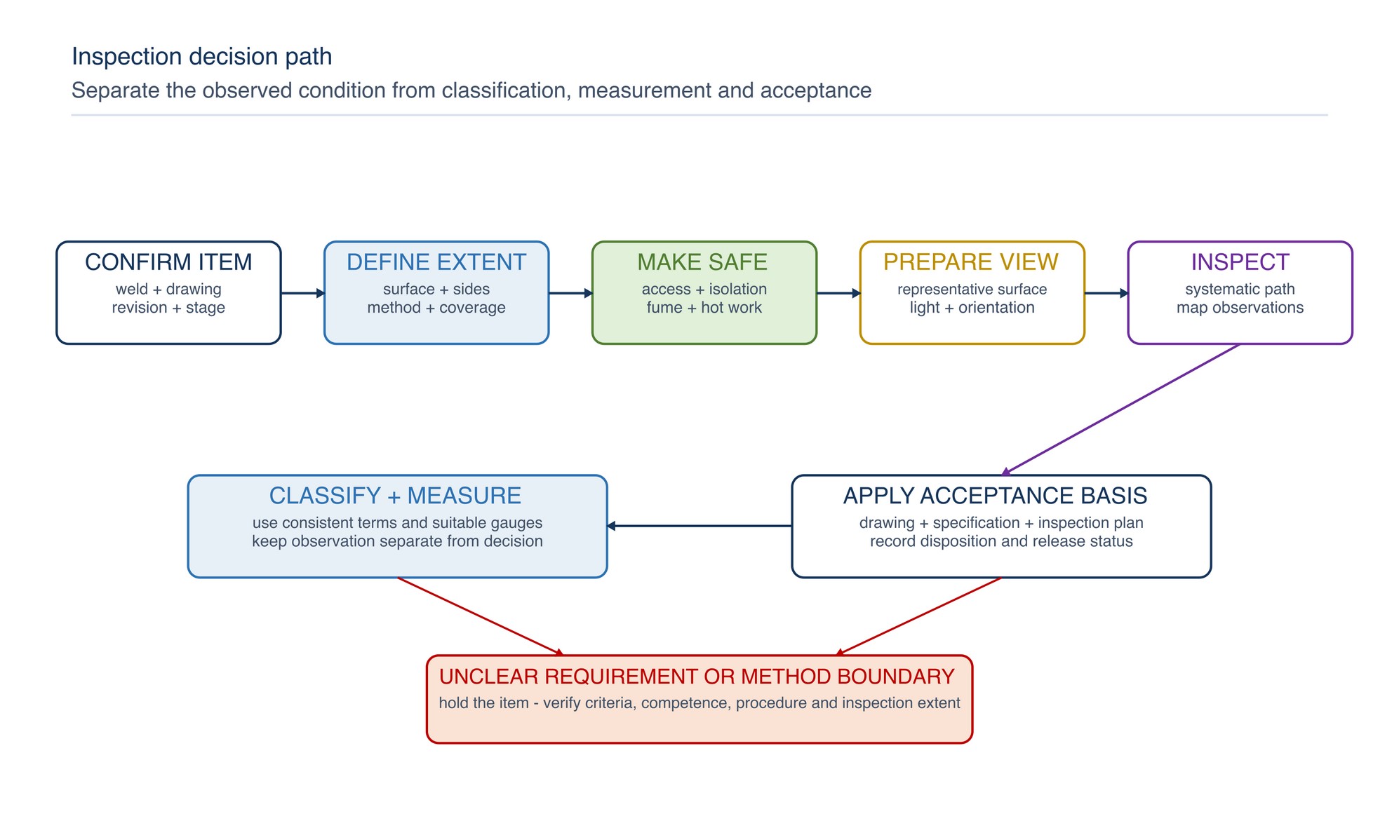
Identification, classification, measurement, testing and acceptance are different steps. Observe the complete required area, describe the condition accurately, and make the decision only against the applicable drawing, fabrication specification, inspection plan and acceptance criteria.
Inspection protects the connection between design intent, fabrication quality and service performance. A quick glance at the weld face is not enough. The inspector needs a defined item and revision, a safe and representative surface, adequate access and visibility, a repeatable coverage path, suitable measuring tools, an acceptance basis and a record that locates every relevant observation. Visual testing is valuable before, during and after welding, but it cannot establish every internal, subsurface or metallurgical condition. [S240; S241]
Chapter objectives
After this chapter, the reader should be able to:
- identify the weld, surface, drawing revision, inspection stage, extent and acceptance basis;
- distinguish an observation, indication, imperfection, measured result and acceptance decision;
- make the area safe and establish representative access, cleanliness and visibility;
- inspect the weld face, toes, starts, stops, craters, transitions, adjacent base metal and accessible reverse side systematically;
- recognise common visible condition families without claiming hidden depth or cause;
- measure specified profile, alignment and local surface characteristics with suitable gauges;
- map an indication by station, side, orientation, length and relationship to the weld zone;
- select the correct boundary between visual inspection and penetrant, magnetic, ultrasonic or radiographic testing;
- prevent grinding and repair from hiding the original condition or reducing required section;
- record inspection method, extent, result, disposition and re-inspection status clearly; and
- stop when access, surface condition, acceptance basis or inspection competence is inadequate.
Begin with the inspection requirement
Before examining the surface, confirm:
- part, assembly, weld and joint identity;
- drawing, weld symbol, fabrication specification and revision;
- material and joint type;
- inspection stage: before welding, during production, after welding, after finishing, after repair or in service;
- required inspection extent and accessible sides;
- specified method, testing level and personnel requirement;
- dimensional and surface characteristics to be assessed; and
- applicable acceptance criteria and disposition route.
Weld symbols can convey geometry, manufacture, quality, testing and surface-finish information. Read the complete symbol system and associated notes; do not interpret one isolated symbol from memory. Where a symbol, finish requirement, testing extent or quality level is unclear, use the controlled drawing and inspection process before proceeding. [S244]
Keep five inspection functions separate
Confusion between description and acceptance creates inconsistent decisions. Use the following sequence:
| Function | Practical question | Output | Important boundary |
|---|---|---|---|
| Observation | What is visible or measurable at this location? | Factual note, image, sketch or value | Avoid assigning cause or acceptability too early |
| Indication | What response or visible feature requires evaluation? | Located indication with method and extent | An indication is not automatically a defect |
| Classification | Which recognised condition or imperfection family best describes it? | Consistent name or classification | Classification does not itself select an acceptance limit |
| Measurement or testing | What size, extent or method response has been established? | Traceable result with unit or technique | A surface result does not prove internal depth |
| Acceptance | Does the result meet the applicable requirement? | Accept, repair, investigate, hold or reject | Use the specified criteria and authorised decision route |
ISO 6520-1 provides a classification basis for geometrical imperfections in fusion welding. ISO 5817 provides quality levels for covered fusion-welded joints, while ISO 17635 links method selection, testing levels and acceptance levels on a general basis. These documents serve different functions; a classification code or quality-level label must not be converted informally into a universal pass/fail rule. [S241; S242; S243]
Make the inspection area safe
Inspection can expose personnel to residual hot-work hazards even when welding has stopped. Confirm the safe system of work before approaching, touching, cleaning, gauging or marking the item.
Control, as applicable:
- movement, stored energy, suspended loads and unstable components;
- hot metal, sharp edges, slag, spatter and recently ground surfaces;
- welding fume, metal dust and residues from coatings or cleaning chemicals;
- sparks, fragments, noise and kickback when preparation or repair grinding is authorised;
- electrical and magnetic equipment;
- penetrant materials, cleaners, developers and ultraviolet sources;
- confined-space entry, atmosphere, access, rescue and communication; and
- radiography exclusion zones and specialist access control.
Do not enter an industrial-radiography controlled area or disturb radiography equipment. Radiography is performed only through the authorised radiation-protection programme, trained personnel and controlled-area arrangements. [S251]
Welding and grinding can involve fumes, UV radiation, fire, sparks, flying fragments and confined-space hazards; use the site's Malaysian risk assessment, permits and control measures. [S252; S253]
Establish a representative surface and clear view
The surface must show the condition being inspected without preparation that destroys evidence. Remove loose slag, dust, oil, marker residue or spatter only to the extent authorised by the inspection plan. Do not grind, peen, polish, pickle, wire-brush or blast an area merely to make it look acceptable.
Before inspection:
- confirm the surface state required by the procedure;
- identify coatings, oxides, heat tint, scale, contamination and previous repairs;
- clean using a compatible method that will not smear metal across a crack, fill a recess or round an edge;
- allow wet surfaces and cleaning residues to reach the required condition;
- use suitable direct or aided viewing access;
- position lighting to reveal profile and surface-breaking features without glare or deep shadow; and
- verify mirrors, borescopes, magnifiers, cameras and measuring aids when the method depends on them.
A photograph is useful evidence but not a substitute for controlled inspection. Include scale, orientation and location, avoid perspective distortion, and retain an unmarked original when annotated copies are used.
Cover the complete specified weld zone
Use a repeatable path rather than looking only at visually prominent areas. Start from a defined end or datum and move along the weld in overlapping inspection fields.
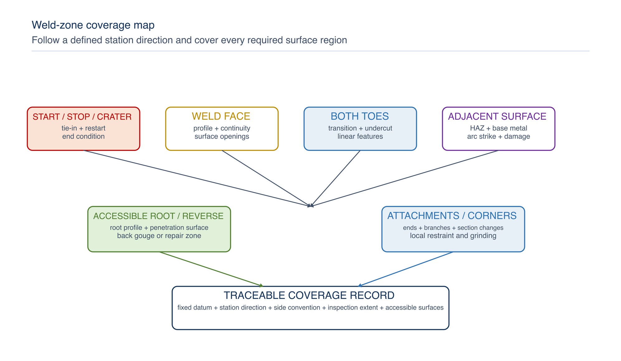
Cover, as required:
- weld face and full length;
- both weld toes and transitions;
- starts, stops, craters, restarts and tie-ins;
- attachment ends, corners, branches and changes in section;
- adjacent heat-affected zones and base metal;
- arc strikes, temporary-attachment locations and ground areas;
- accessible root, penetration surface or reverse side; and
- surrounding surface affected by distortion, handling or finishing.
Mark the station direction and side convention before recording. On circular welds, define a clock position or angular datum. On long welds, use station distances from a fixed reference. Avoid descriptions such as “near the left end” when the item can be rotated or installed differently.
Recognise visible condition families
Describe what can be supported by the visible surface. Do not infer internal penetration, fusion, toughness, hardness or crack depth from surface appearance alone.
| Visible condition family | What to observe | Useful record | What visual inspection cannot establish alone |
|---|---|---|---|
| Crack-like or linear feature | Sharp linear path, branching, crater or toe origin, direction and continuity | Exact start/end, orientation, image and surface condition | True depth, internal extent or cause |
| Weld profile | Face shape, reinforcement, concavity, convexity, transition and symmetry | Cross-section location and specified gauge result | Internal fusion or root condition when inaccessible |
| Undercut or groove | Position at toe or root, continuity and local depth where measurable | Side, station, length and measured characteristic | Hidden continuation beneath the surface |
| Overlap or poor transition | Rolled edge, abrupt toe, lack of smooth fusion appearance | Location, direction and profile image | Bond condition below the visible edge |
| Porosity or cavity | Number, grouping, distribution and open surface size | Mapped area and individual/group description | Subsurface population or internal volume |
| Incomplete fill or crater | Depression, unfilled end, local contour and tie-in | Station, measured profile and adjacent features | Internal soundness |
| Misalignment or distortion | Offset, angular change, bow, twist or local shrinkage | Datum, direction, span and dimensional method | Residual stress or service fitness |
| Arc strike, spatter or surface damage | Location, density, gouge, indentation or thermal mark | Surface map and relationship to required finish | Metallurgical effect without further evaluation |
| Grinding or blending mark | Direction, depth appearance, edge radius and remaining profile | Before/after images and local thickness where required | Remaining section or crack removal without measurement/testing |
Use neutral wording: “linear surface indication at the upper toe from station 420 to 437 mm” is more useful than “bad crack near the end.” If an authorised classification is required, apply it after the observation is located and described. [S243]
Select the inspection method by the question
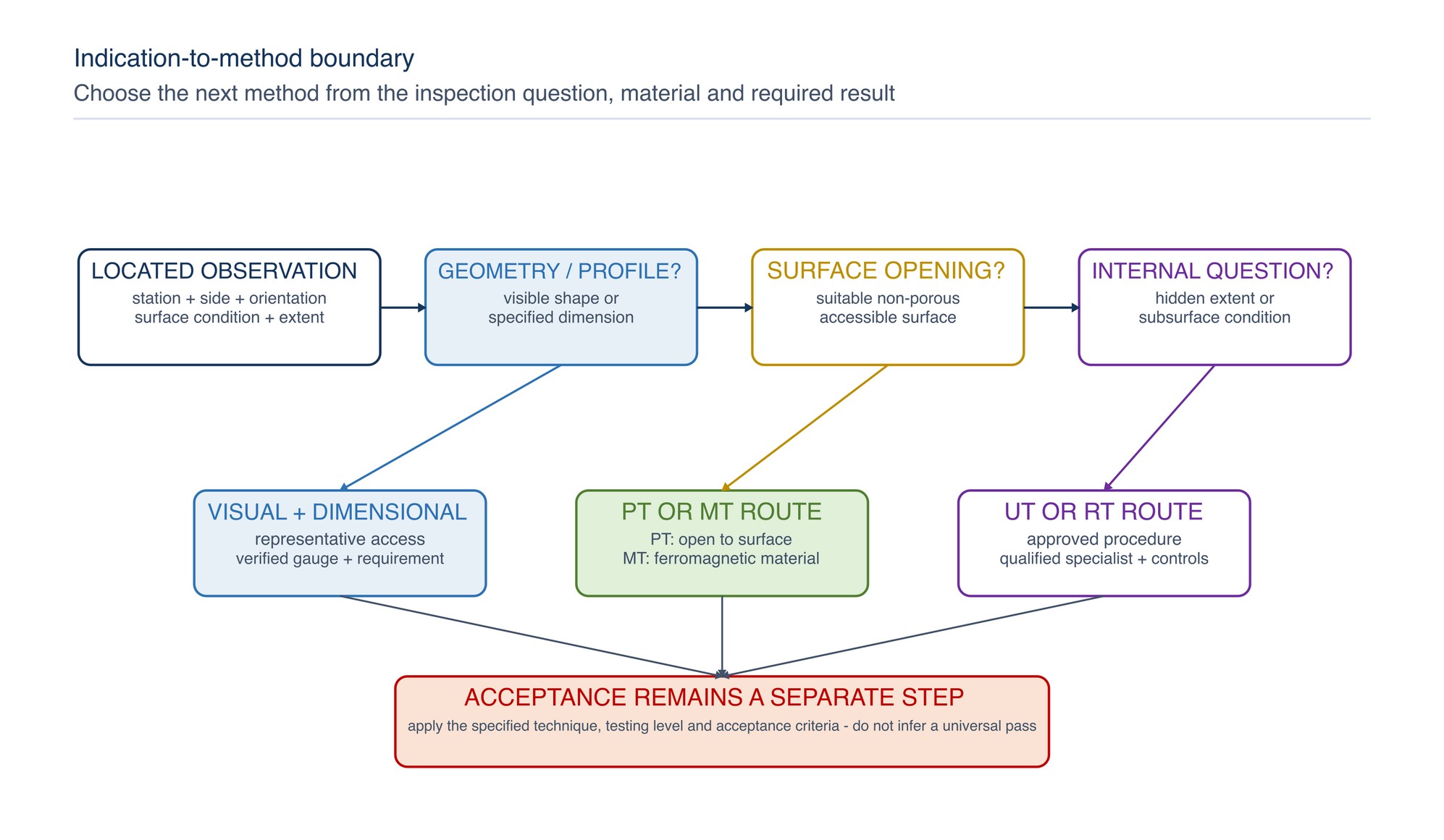
No single NDT method answers every question. ISO 17635 selects methods in relation to quality requirements, material, weld thickness, welding process and testing extent. [S241]
| Method | Primary application | Material/surface boundary | Typical output boundary |
|---|---|---|---|
| Direct visual and dimensional inspection | Accessible surface condition, profile, dimensions and visible discontinuities | Requires representative access and visibility | Cannot establish hidden depth or internal soundness |
| Penetrant testing | Discontinuities open to a suitable non-porous surface | Test material must be compatible with the penetrant system; surface openings must remain accessible | Indication reveals surface opening, not depth or automatic acceptability |
| Magnetic particle testing | Surface-breaking and some shallow subsurface discontinuities | Ferromagnetic material only; orientation and magnetisation matter | Sensitivity reduces rapidly with depth; acceptance is separate |
| Ultrasonic testing | Internal reflectors and thickness-related questions through an applicable weld technique | Material, thickness, geometry, surface and procedure suitability matter | Specialist interpretation; not a simple picture of defect shape |
| Radiographic testing | Internal volumetric and profile-related information through controlled X-ray or gamma techniques | Joint geometry, thickness, access and radiation controls | Specialist regulated activity with exclusion zones |
The exact method, equipment, consumables, sensitivity, technique, testing level and acceptance level are controlled by the applicable procedure. Refer to the product label, Technical Data Sheet, or MKTECH representative.
Inspect before and during welding where required
Pre-weld inspection can prevent later conditions that are difficult to correct. ISO 17637 may be applied to visual testing of the joint before welding. [S240]
Check, as specified:
- correct material and joint identity;
- joint preparation, root face, root gap and included angle;
- alignment, mismatch, fit-up and restraint;
- cleanliness, moisture, coatings and contamination;
- tack weld location, condition and integration plan;
- backing, inserts, purge arrangements or consumable supports;
- accessibility for welding and later inspection;
- weld sequence, distortion controls and temporary attachments; and
- traceability marks that must remain visible.
During production, inspect hold points defined by the fabrication plan. Do not disturb hot work or enter the welder's controlled area merely to observe. Record the stage at which an observation was made because later passes can cover earlier surfaces.
Inspect the weld face, toes and transitions
View the weld from more than one angle. Low-angle lighting can reveal profile changes; more direct lighting can reveal surface texture and colour differences. Change position rather than relying on glare.
Follow this sequence:
- survey overall continuity, alignment and distortion;
- examine the full face for profile, cavities, inclusions open to the surface and irregular stops;
- trace each toe continuously;
- examine starts, stops, craters, restarts and tie-ins;
- inspect adjacent base metal for arc strikes, gouges, spatter, damage and grinding;
- inspect the accessible reverse side or root condition; and
- revisit mapped indications with the specified gauge or follow-up method.
Do not accept a smooth face as proof of sound fusion. Conversely, do not reject an irregular but permitted profile without comparing it with the actual requirement.
Measure only the specified characteristic
Use a suitable verified gauge and a defined reference. Chapter 041 covers basic dimensional principles; this chapter applies them to weld inspection.
| Characteristic | Practical method | Setup control | Common error |
|---|---|---|---|
| Fillet weld size or throat-related feature | Specified weld gauge or dimensional construction appropriate to the drawing | Confirm weld type, symbol convention and reference surfaces | Treating leg length and throat as interchangeable |
| Reinforcement or face height | Bridge or profile gauge from sound adjacent surfaces | Avoid rocking on spatter, scale or distorted base metal | Using a damaged local surface as the datum |
| Undercut depth | Suitable gauge across a representative reference surface | Measure the actual groove normal to the intended surface | Confusing shadow or oxide boundary with depth |
| Root gap or fit-up before welding as specified | Feeler, taper or dedicated gap gauge | Avoid forcing the joint apart or measuring over tack distortion | Reporting one accessible point as the complete joint |
| Misalignment or offset | Straightedge, bridge gauge, calliper or dimensional system | Define the two surfaces, direction and station | Mixing angular distortion with local offset |
| Angular distortion or bow | Straightedge, level, fixture or coordinate method over a defined span | Support the item consistently and record datum/span | Flattening the part during measurement |
| Local thickness after grinding | Suitable thickness method at mapped locations | Establish original/nominal requirement and surface access | Assuming visual blending preserved section |
Record the gauge identity, location, orientation, unit and observed value. Do not use an unverified multipurpose gauge merely because it produces a number.
Map indications so they can be found again
An inspection record must allow another competent person to return to the same feature. Use:
- weld or joint identifier;
- station measured from a fixed datum;
- arrow side/other side, face/root or a documented side convention;
- clock position for circumferential joints;
- distance from weld centreline or toe;
- indication length, direction and distribution;
- relationship to start, stop, crater, attachment or repair;
- surface condition and inspection method; and
- image or sketch reference.
Marking paint, chalk or metal stamps can interfere with later NDT or damage the part. Use the authorised marking method and preserve traceability through cleaning, repair and finishing.
Control grinding, blending and repair
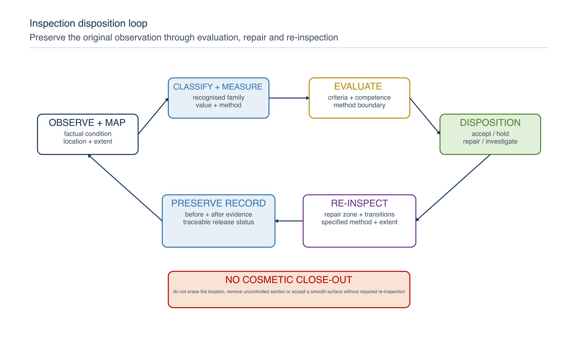
Grinding can expose a condition, remove it, smear metal across it, reduce section, change toe geometry or erase the original location. Treat repair preparation as a controlled manufacturing step, not as cosmetic tidying.
Before grinding:
- record and map the original condition;
- confirm repair authorisation and permitted extent;
- identify minimum thickness, profile and transition requirements;
- control sparks, fragments, dust, heat and contamination;
- select an abrasive and tool suitable for the material and access; and
- define the re-inspection method and extent.
During grinding, use light progressive removal and inspect frequently. Avoid deep grooves, sharp notches, overheating, excessive pressure and uncontrolled widening. After grinding, clean the area, verify remaining profile or thickness as required, and re-inspect the repaired zone plus affected transitions. A visually smooth repair is not evidence that a crack or internal condition has been removed.
Use penetrant testing within its boundary
Penetrant testing detects discontinuities open to the surface on suitable materials using visible or fluorescent systems. It can reveal cracks, laps, folds, porosity and lack-of-fusion conditions only where they communicate with the surface. The term discontinuity does not by itself state acceptability. [S245]
The controlled procedure governs:
- material and product compatibility;
- cleaning and drying;
- penetrant family and sensitivity;
- application, dwell, removal and development;
- viewing conditions and timing;
- control checks and reference materials;
- interpretation and acceptance criteria;
- post-cleaning and corrosion/contamination control; and
- operator qualification.
Do not mix products from different systems casually, substitute household cleaners, guess dwell times or apply penetrant to an excessively rough, porous, contaminated or hot surface outside the procedure. Penetrant acceptance levels for welds are addressed separately from the general method principles. [S248]
Use magnetic particle testing within its boundary
Magnetic particle testing is for ferromagnetic materials. It is primarily used for surface-breaking discontinuities, particularly cracks, and may detect some shallow subsurface discontinuities; sensitivity reduces rapidly with depth. [S246]
Weld testing can cover the weld and heat-affected zones using techniques suited to the joint and likely discontinuity orientation. Magnetisation direction, field strength, surface condition, detection medium, lighting, demagnetisation and recording are controlled by the procedure. ISO 17638 does not itself specify acceptance levels; those are addressed separately or by the product/application standard. [S247; S249]
Do not apply magnetic testing to non-ferromagnetic alloys, infer depth from indication intensity, or accept one field direction when the procedure requires coverage of different orientations. Keep sensitive equipment, electronic devices and magnetically affected parts within site controls.
Route internal-condition questions to specialist NDT
Visual, penetrant and magnetic methods do not provide universal assurance of internal weld soundness. Possible internal lack of fusion, incomplete penetration, inclusions, volumetric porosity or cracking may require ultrasonic or radiographic testing selected through the applicable code, material, thickness, geometry and quality requirement. [S241]
Specialist NDT requires an approved written procedure, suitable equipment and calibration/reference arrangements, defined testing and acceptance levels, and competent personnel. ISO 9712 provides a qualification and certification framework for industrial NDT personnel but the required scheme and authorisation remain contract and jurisdiction dependent. [S250]
Do not:
- request “an X-ray” as a universal answer;
- enter radiography barriers or rely on warning signs alone;
- interpret an ultrasonic screen or radiograph without the required competence;
- convert an NDT indication into a fabrication cause without evaluation; or
- assume a result from one method closes questions outside that method's capability.
Record a reconstructable inspection result
Include, as applicable:
- job, part, assembly and weld identity;
- drawing, specification, inspection-plan revision and acceptance basis;
- material, joint type and welding/repair stage;
- inspection date, operator and competence/authorisation reference;
- method, technique, extent and accessible sides;
- surface condition, access and viewing aids;
- measuring or NDT equipment identity and status;
- station convention and indication map;
- observation, classification and measured result with units;
- image, sketch or report references;
- decision and authorised disposition;
- repair reference and re-inspection method/extent; and
- final release, hold or escalation status.
Keep the original observation separate from later annotations and disposition. If an indication changes after cleaning or grinding, retain the before-and-after record rather than replacing the original description.
Troubleshoot inconsistent inspection results
| Observation | Likely causes | Practical correction |
|---|---|---|
| Feature appears only from one viewing angle | Glare, shadow, surface texture or very shallow geometry | Change lighting and viewing direction; clean only as authorised and map the feature |
| Different inspectors locate different extents | Undefined datum, inconsistent surface preparation or overlapping fields | Establish station/side convention and a repeatable coverage path |
| Gauge result changes with position | Real profile variation, rocking, spatter or poor datum contact | Map several stations; clean reference contacts and verify gauge seating |
| Linear feature disappears after brushing | Loose residue, smeared metal or insufficiently controlled preparation | Preserve the original record and route to the specified follow-up method |
| Penetrant background obscures indications | Rough/porous surface, poor cleaning/removal or unsuitable system/application | Stop and repeat only under the approved procedure with suitable surface and controls |
| Magnetic indication appears in one direction only | Discontinuity orientation relative to the magnetic field | Apply the required multi-direction technique through qualified personnel |
| Ground repair looks smooth but thickness is uncertain | Uncontrolled removal or distorted reference surface | Measure remaining section with a suitable method and compare with the requirement |
| Repaired area cannot be relocated | Marking removed and no station record | Re-establish traceability from fixed datums before further work |
| Visual result conflicts with specialist NDT | Different method capability, location error or interpretation boundary | Reconcile item, extent, coordinate system, procedure and acceptance basis |
| Acceptance decision varies by person | Criteria, quality level or authority not defined | Use the controlled inspection plan and authorised disposition route |
Practical inspection and release checklist
Before releasing the inspection result, confirm:
- the correct item, weld, drawing and revision were used;
- the inspection stage, required extent, accessible sides and acceptance basis were clear;
- the area was safe to access and specialist exclusion zones were respected;
- the surface condition and visibility were suitable for the method;
- the complete weld face, toes, starts, stops, transitions and required adjacent areas were covered;
- the accessible root or reverse side was inspected where required;
- observations were factual, located and kept separate from acceptance decisions;
- specified dimensions were measured with suitable verified tools and recorded with units;
- indication station, side, orientation, length and relationship to the weld zone were mapped;
- visual inspection was not used to claim hidden depth, internal soundness or metallurgy;
- penetrant, magnetic, ultrasonic or radiographic work followed the approved qualified-person route;
- original conditions were recorded before grinding or repair;
- remaining profile or thickness was checked where material was removed;
- repaired areas and affected transitions were re-inspected to the specified extent;
- the applicable acceptance criteria and authorised disposition were applied; and
- the final record supports traceability, review and release.
Correct Use of Calipers and Micrometers
This next-chapter title appears on the following page of the printed handbook (page 364), outside this chapter extract.