
Factory owners, production managers, workshop supervisors, maintenance teams, operators, safety and health personnel, technical buyers and application personnel responsible for portable and stationary grinding equipment
Asset control; maintenance planning; competence; hazardous-energy isolation; cleaning; inspection; guards and controls; spindles, flanges, bearings and drives; electric, battery and pneumatic tools; stationary machines; extraction and coolant; condition monitoring; defect priority; repair release; records and troubleshooting.
After maintenance, test every affected protective function under controlled conditions before production release. A guard refitted without its fasteners, an interlock defeated for testing or a switch that works intermittently is not an acceptable temporary condition.
A switch, emergency stop or software command is not automatically an energy-isolating device.
Preventive maintenance is complete only when the machine is safe to maintain, the required work is performed correctly, every protective function is restored, and the machine passes a controlled return-to-service check.
Grinding machines operate in a severe environment of abrasive dust, impact, vibration, heat and repeated load. Small deterioration can affect guarding, mounting accuracy, wheel life, surface finish, noise, vibration and productivity before a breakdown occurs. A strong maintenance system combines operator care, planned inspection, competent technical work, condition monitoring and disciplined defect closure. [S275; S284; S286; S329]
Chapter objectives
After this chapter, the reader should be able to:
- establish a controlled identity and maintenance basis for each machine;
- set task content and frequency from risk, duty and condition;
- separate operator checks, competent maintenance and specialist repair;
- isolate electrical, pneumatic, mechanical and stored energy safely;
- clean equipment without spreading hazardous dust or damaging components;
- inspect guards, controls, spindles, flanges, bearings, drives and supports;
- apply relevant branches for portable, pneumatic and stationary machines;
- recognise condition indicators before failure;
- classify defects and prevent unsafe reissue;
- control replacement parts and repair quality;
- complete a staged return-to-service check; and
- improve the maintenance plan from history and recurring faults.
Build one maintenance control system
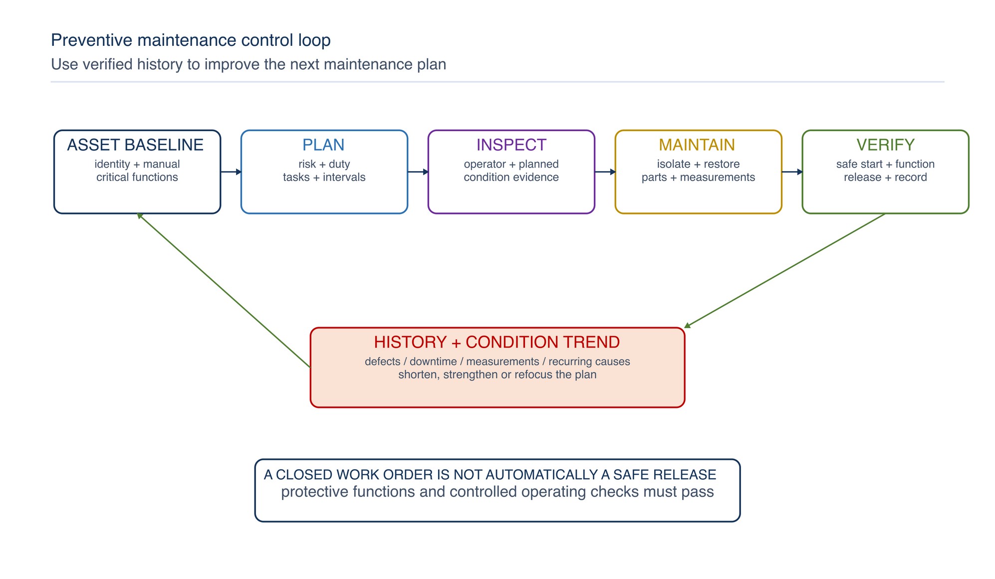
Preventive maintenance has four connected layers:
| Layer | Primary purpose | Typical output |
|---|---|---|
| Operator care | Detect visible deterioration and abnormal behaviour early | Pre-use check, cleaning within authority, defect report |
| Planned inspection | Examine defined safety and condition points at suitable intervals | Inspection result, measured condition, work request |
| Preventive task | Restore or preserve a defined function before failure | Adjustment, lubrication, replacement, cleaning, calibration or test |
| Condition-based action | Respond to a meaningful trend or abnormal event | Investigation, controlled shutdown, repair or interval change |
These layers should share one defect and release process. A clean machine is not necessarily serviceable, and a completed work order is not a release if the guard, control, extraction or mounting system has not been verified.
Establish the asset baseline
Create a reliable machine record before planning maintenance. Identify:
- asset number, location and responsible owner;
- manufacturer, model and serial number;
- machine type and intended operations;
- electrical, battery, pneumatic, hydraulic or other power source;
- rated capacity and maximum no-load speed information;
- spindle, arbor, flange, chuck, collet or mounting system;
- guard, handle, work-rest, interlock and emergency-control arrangement;
- extraction, coolant, filtration or lubrication system where fitted;
- applicable instruction, parts and service documents;
- authorised accessories and replacement components;
- commissioning, modification, repair and inspection history; and
- critical production and safety functions.
Keep markings legible. Do not create a new rating plate, guess a model from appearance or transfer a specification from a similar machine. Refer to the product label, Technical Data Sheet, or MKTECH representative.
Set priorities from risk and criticality
Maintenance attention should reflect the consequence and likelihood of failure, not only the purchase price of the machine.
| Factor | Higher-priority examples | Planning effect |
|---|---|---|
| Safety consequence | Guard, spindle, wheel mounting, control or emergency-stop failure | Shorter review cycle and defined release authority |
| Duty severity | Multiple shifts, heavy contact, high dust, frequent starts or mobile use | More frequent cleaning and condition checks |
| Environment | Moisture, corrosive residue, outdoor work, heat or conductive dust | Environmental protection and targeted inspection |
| Process sensitivity | Tight finish, run-out or dimensional requirement | Baseline measurement and trend monitoring |
| Failure history | Repeated bearing, switch, cable, hose or tracking defects | Root-cause action and revised task content |
| Production impact | Bottleneck machine or no ready backup | Planned access, critical spares and condition monitoring |
Do not extend a maintenance interval simply because the machine has not failed. Review inspection findings, near misses, product changes, repair history and operating severity together. [S330; S332]
Define roles and competence
Match work authority to risk and technical complexity.
- Operator: pre-use checks, approved external cleaning, correct accessory change and prompt defect reporting.
- Supervisor or issuer: asset status, quarantine, work allocation, inspection confirmation and operating release within the site system.
- Maintenance technician: planned tasks, isolation, adjustment, component replacement, measurement and functional verification within competence.
- Electrical or specialist technician: internal electrical work, protective-device testing, controller work, major spindle or drive repair and calibrated acceptance tests.
- Manufacturer or authorised service provider: work reserved by the manual, warranty conditions, special tooling, firmware, safety electronics or proprietary assemblies.
Competence includes knowing when not to proceed. An operator who can change a wheel is not automatically authorised to dismantle a spindle, repair a guard, alter an interlock or adjust a speed controller. [S329; S333; S334]
Plan and isolate maintenance safely
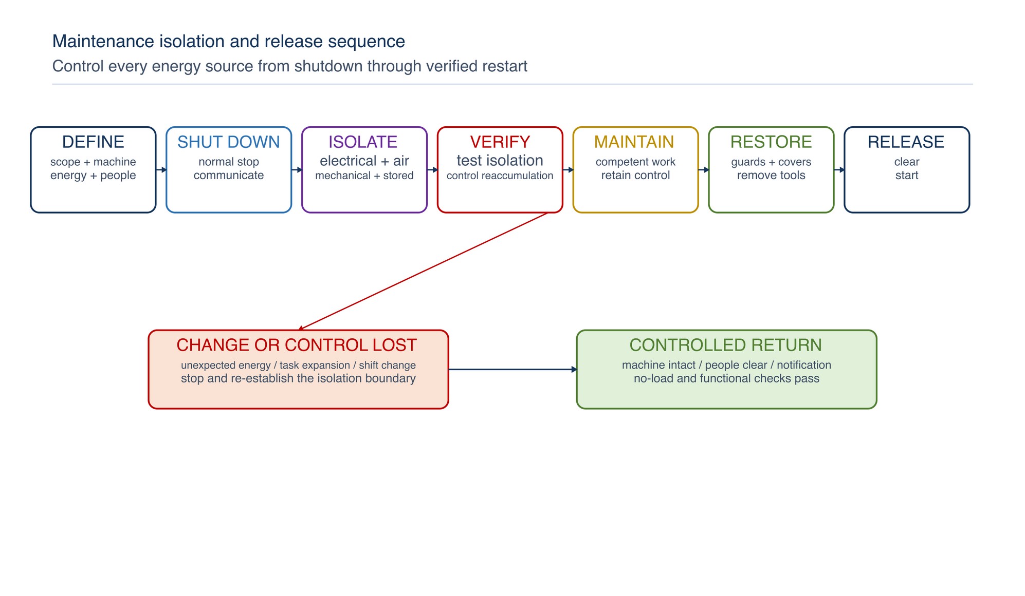
Maintenance may expose rotating parts, stored pressure, gravity, springs, heat, sharp edges, electricity, automatic movement and hazardous deposits. Prepare the job before opening the machine.
- Define the work scope and affected equipment.
- Identify every energy source and possible reaccumulation.
- Shut down by the normal stopping method.
- Isolate energy using the workplace procedure.
- Release, block or restrain stored energy.
- Verify that isolation is effective before work begins.
- Control adjacent machines, connected extraction, automatic feeders and remote starts.
- Maintain isolation through shift, contractor and group changes.
Removing a battery, unplugging a cord or closing an air valve is effective only when it controls all relevant energy and remains under the required control. A switch, emergency stop or software command is not automatically an energy-isolating device. [S275; S331]
Clean without creating a second hazard
Cleaning protects cooling, movement, visibility and inspection, but poor methods can force dust into bearings, motors, switches or the breathing zone.
Use a method compatible with the machine and deposit:
- isolate before opening guards, covers, filters or collection points;
- capture dust with suitable extraction or vacuum equipment;
- avoid uncontrolled compressed-air blowing and dry sweeping;
- keep ventilation slots and cooling paths clear without pushing debris deeper;
- use only cleaning agents compatible with plastics, insulation, seals, coatings and lubricants;
- keep liquids away from electrical assemblies unless the procedure permits them;
- control metal, coating, compound and combustible-dust mixtures;
- inspect hidden ledges, enclosures, ducts and base cavities;
- dispose of collected material by its actual composition; and
- allow all parts to dry and restore covers before energising.
Clean enough to inspect. A polished exterior should not conceal blocked ventilation, loaded extraction, damaged wiring or contaminated mounting faces. [S320; S329; S333; S334]
Maintain guards, controls and protective devices
Treat these items as safety-critical:
- wheel and belt guards, covers and enclosures;
- auxiliary handles, handholds and tool rests;
- start, stop, hold-to-run and lock-off controls;
- emergency stops and braking functions;
- interlocks, presence sensing and access switches;
- spark, chip and transparent screens;
- overspeed, overload, anti-restart and other protective functions where fitted; and
- labels, direction arrows and warnings.
Inspect for cracks, distortion, looseness, missing fasteners, unauthorised holes, bypasses, slow return, sticking or unreliable operation. Replace a damaged guard with the correct component; do not weld, hammer, trim or drill it unless an approved repair procedure specifically permits the work.
After maintenance, test every affected protective function under controlled conditions before production release. A guard refitted without its fasteners, an interlock defeated for testing or a switch that works intermittently is not an acceptable temporary condition.
Protect spindle and mounting accuracy
The spindle–flange–abrasive interface transfers speed and load while controlling alignment.
Check, as applicable:
- spindle or arbor straightness and run-out;
- thread form, shoulder and locating diameter;
- flange flatness, matching, contact surfaces and retention;
- chuck, collet, mandrel or hub wear;
- key, taper and locking mechanism condition;
- axial and radial play;
- mounting-face contamination, burrs and impact damage; and
- free rotation and clearance after assembly.
Do not dress a damaged flange with an improvised hand method, force a nut over damaged threads or use packing to remove looseness. Quantitative checks require the correct instrument, setup and acceptance value. Refer to the product label, Technical Data Sheet, or MKTECH representative.
Inspect bearings, gears, belts and drives
Rotating components often signal deterioration through changing sound, vibration, heat, backlash, leakage or load behaviour.
| Indicator | Possible system area | Maintenance direction |
|---|---|---|
| Rumbling or rough rotation | Bearing, contamination, lubrication or fit | Isolate and inspect; do not mask with additional lubricant |
| Gear noise or backlash change | Gear wear, lubrication, alignment or damage | Inspect drive and lubricant condition using the service method |
| Belt dust, slip or tracking drift | Tension, pulley alignment, contamination or wear | Correct cause; replace matched components where required |
| Hot housing | Load, bearing, cooling, lubrication or electrical condition | Stop and compare with baseline; investigate before restart |
| Repeated fastener loosening | Vibration, damaged thread, joint design or incorrect assembly | Identify cause; use the specified fastener and retention method |
| Oil or grease leakage | Seal, fill level, pressure, breathers or over-lubrication | Control contamination and restore the specified sealing system |
Lubrication is product-specific. More grease or oil can increase heat, attract abrasive contamination, damage seals or affect braking. Use the specified lubricant, quantity, point and method.
Portable electric grinder branch
For corded tools, include:
- lead, plug, strain relief and external insulation;
- switch and anti-restart behaviour where fitted;
- vents, fan path and brush area;
- brush wear or automatic brush shut-off where the design uses brushes;
- spindle lock, guard clamp and side-handle threads;
- gearbox leakage, noise and play; and
- applicable electrical inspection and test.
For battery tools, also inspect:
- battery case, contacts, latch and contamination;
- charger, lead and ventilation;
- heat, swelling, impact or liquid exposure;
- battery seating and retention; and
- protective cut-out or brake behaviour described by the manual.
Do not open a battery pack, bypass protective electronics or clean electrical tools with flammable solvent. Internal repair and electrical testing should follow the actual tool instructions and competent service process. [S283; S334]
Pneumatic grinder branch
Pneumatic-tool maintenance should consider the complete air system:
- hose, coupling, whip restraint and inlet condition;
- pressure control, filter, regulator and lubricator where applicable;
- air quality, moisture and contamination;
- throttle, lock-off, governor and exhaust;
- spindle, collet and guard;
- free-speed verification after relevant work and at the specified interval;
- vibration, noise and leakage; and
- specified lubrication.
Turn off the supply, bleed pressure and disconnect before accessory change or maintenance. A speed controller or governor is a safety-relevant assembly and should not be improvised, altered or dismantled beyond authorised instructions. Use a calibrated tachometer and the specified no-accessory method when a free-speed check is required. [S280; S333]
Stationary grinding-machine branch
For bench, pedestal, cut-off and larger stationary grinding machines, include the installed system:
- foundation, anchorage and machine stability;
- wheel enclosure, guard, doors and fasteners;
- work rest, tongue or opening controls and adjustment locks;
- spindle, bearings, flanges and drive;
- brake, start, stop and emergency controls;
- screens, lighting and visibility;
- wheel-change lifting or handling arrangements;
- extraction, spark collection, coolant and filtration;
- workholding, tables, slides, feeds and limit devices; and
- automatic cycle, interlock and safe-access functions.
Adjustments made after wheel wear must preserve the required machine arrangement and clearance. Perform them only while safely stopped and isolated as required. Machine-specific numeric values follow the current instructions and workplace procedure. [S284; S286; S287]
Maintain extraction, coolant and collection systems
A grinding machine may be mechanically sound while its supporting controls are ineffective.
Check extraction hoods, dampers, ducts, flexible connections, filters, separators, waste containers and airflow indicators. Look for blocked branches, leaks, spark damage, deposits, incompatible material mixing and unauthorised changes. A stronger fan does not correct an unsuitable collector or hazardous dust combination.
Where coolant is used, control:
- concentration or condition by the approved method;
- flow, nozzle position and return path;
- filtration, tramp oil and solids loading;
- tank cleanliness and biological deterioration;
- leaks, hose damage and slip hazards;
- compatibility with the abrasive and work material; and
- mist control and enclosure condition.
Coordinate machine and extraction maintenance so one system is not released while the other remains unavailable.
Use condition monitoring intelligently
Condition monitoring compares repeatable indicators against an established baseline and decision process. It may include:
- vibration at defined locations and operating conditions;
- bearing or housing temperature;
- acoustic or ultrasonic behaviour;
- spindle run-out and wheelhead movement;
- motor current, power or cycle behaviour;
- pneumatic free speed and air consumption;
- lubricant or wear-debris condition;
- extraction airflow or pressure indication; and
- process signals such as finish drift, burn, chatter, loading or cycle-time change.
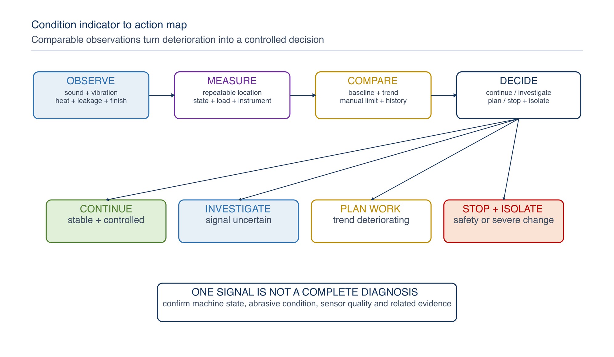
Do not diagnose a bearing, wheel or motor from one signal alone. Confirm sensor location, machine state, load, abrasive condition and measurement quality. A trend is useful only when readings are comparable. [S332]
Set and improve maintenance intervals
Use the shortest applicable requirement from manufacturer instructions, workplace controls, statutory inspection, warranty or risk assessment. Then refine the programme with actual history.
Consider:
- operating hours, cycles, starts and shifts;
- abrasive dust quantity and type;
- contact load and thermal severity;
- portable, outdoor or corrosive exposure;
- operator reports and pre-use findings;
- measured condition trends;
- time since repair or modification;
- failure consequence and spare availability; and
- evidence of stable or accelerating deterioration.
Intervals may be shortened when defects recur or conditions become more severe. They may be reviewed when history consistently shows negligible deterioration, but only through a controlled risk-based decision. Avoid creating excessive low-value checks that encourage superficial completion. [S330]
Classify defects and control machine status
| Defect class | Examples | Status action |
|---|---|---|
| Immediate safety defect | Guard missing, control unreliable, spindle loose, exposed conductor, severe air leak, abnormal free speed | Stop, isolate and quarantine |
| Degraded safety function | Intermittent brake, cracked screen, loose work rest, damaged extraction connection | Remove from production and arrange competent correction |
| Developing condition | Rising vibration, heat, leakage, belt dust, finish drift or repeated loading | Plan investigation promptly and define operating restrictions only through authorised assessment |
| Housekeeping or minor condition | External dirt, label beginning to fade, non-critical loose cover fastener | Correct within the assigned period and recheck |
| Recurring defect | Same component or symptom repeats after repair | Escalate to root-cause review; do not continue parts replacement alone |
Status should be visible at the machine and in the maintenance system. Prevent an isolated or quarantined machine from being restarted, moved or reissued without formal release.
Control repairs and replacement parts
Before repair, confirm the exact machine identity, revision and parts basis. Use components that match the design and safety function. Check part number, material, rating, dimensions, firmware or configuration where relevant.
Do not:
- substitute a guard, flange, switch, cable, bearing or fastener by appearance;
- bypass an interlock because the correct part is delayed;
- re-machine a safety-critical component without an approved specification;
- mix unmatched bearing or flange components;
- alter cooling, speed or control settings to compensate for wear; or
- return an incomplete machine for “light duty only” without a controlled engineering decision.
Record the fault found, work performed, parts fitted, measurements, tests and person releasing the machine. Retain removed safety-critical parts where investigation or warranty review requires them.
Complete a staged return to service
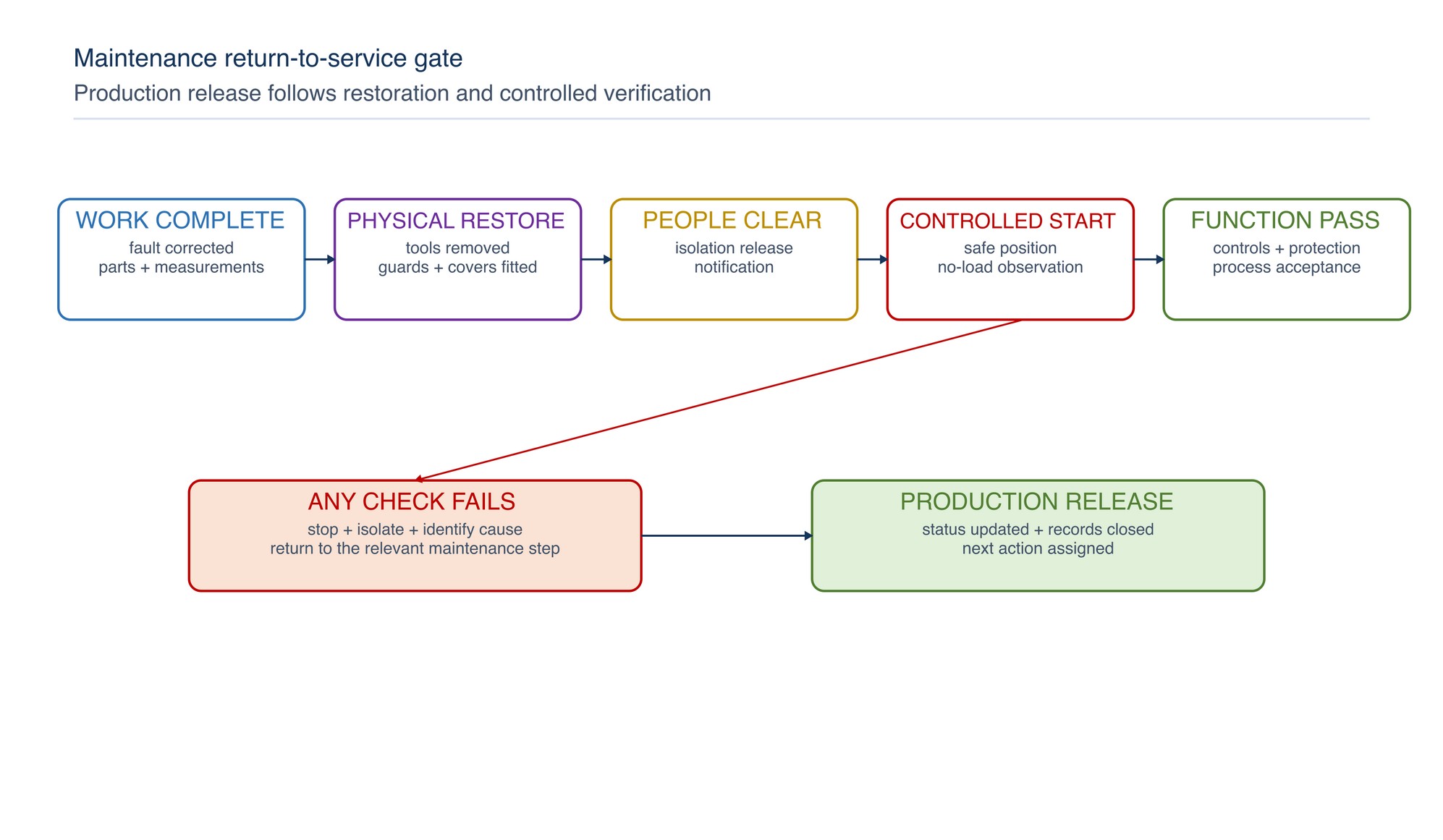
Use this sequence:
- Confirm the planned work and defect corrections are complete.
- Remove tools, loose parts, temporary leads, cleaning materials and blocks.
- Check fluids, fasteners, covers, guards, handles and work supports.
- Restore interlocks, extraction, coolant and protective functions.
- Confirm the machine is operationally intact and the area is clear.
- Follow the workplace process for removing isolation and notifying affected people.
- Energise under controlled conditions from a safe position.
- Conduct required no-load, speed, direction, vibration, leakage and control checks.
- Test the affected function and stop arrangements.
- Release for production only when acceptance criteria pass and records are closed.
If a check fails, stop, isolate and return to maintenance. Production demand does not reduce the release criteria. [S331]
Troubleshoot maintenance-system failures
| Symptom | Likely system issue | Corrective direction |
|---|---|---|
| Repeated emergency repairs | Plan ignores duty, failure history or early indicators | Review criticality, task content and interval |
| Machine clean but overheats | Internal blockage, load, bearing, fan or electrical condition | Compare with baseline and inspect the complete cooling/load path |
| New bearing fails early | Contamination, fit, alignment, lubrication or installation damage | Protect the work, verify method and investigate root cause |
| Wheel run-out after service | Spindle, flange, mounting face, assembly or wheel condition | Isolate and measure the complete mounting chain |
| Belt repeatedly tracks off | Pulley/contact wheel alignment, tension, wear or structure | Correct geometry and cause; do not guide by guard contact |
| Guard fasteners loosen | Vibration, thread damage, wrong fastener or incorrect assembly | Restore specified joint and investigate vibration |
| Pneumatic speed changes | Governor, pressure, air quality, leakage or load | Remove accessory, use authorised checks and competent repair |
| Dust returns after cleaning | Capture, duct, filter, sealing or cleaning method is ineffective | Correct source and system; do not increase blowing |
| Defects appear soon after release | Incomplete verification, wrong part or hidden cause | Re-isolate, review repair scope and strengthen the release gate |
| Interval or part value is uncertain | Machine-specific information is required | Refer to the product label, Technical Data Sheet, or MKTECH representative. |
Preventive-maintenance release checklist
- [ ] Correct machine, model, serial number and work scope are confirmed.
- [ ] Applicable instructions, parts basis and acceptance criteria are available.
- [ ] All energy sources and stored energy are isolated and verified.
- [ ] Dust, residues, sharp parts, heat and maintenance access are controlled.
- [ ] Guards, controls, handles, supports and protective functions are inspected.
- [ ] Spindle, flanges, threads, bearings, drives and mounting faces are serviceable.
- [ ] Electrical, battery, pneumatic or other power-system checks are complete.
- [ ] Extraction, coolant, filtration and collection systems are restored where fitted.
- [ ] Correct parts, lubricants, fasteners and assembly methods were used.
- [ ] Required quantitative checks used suitable calibrated equipment.
- [ ] Tools, loose parts, temporary controls and cleaning materials are removed.
- [ ] Covers, guards, interlocks and emergency controls are fully restored.
- [ ] People are clear and affected personnel are notified before energisation.
- [ ] Controlled no-load and functional checks pass without abnormal condition.
- [ ] Defects, work, parts, measurements, release and next due action are recorded.
Pneumatic Tool Maintenance
The next chapter, Pneumatic Tool Maintenance, begins on the following page of the printed handbook (page 471), outside this chapter extract.