
Production engineers, supervisors, operators, QA/QC personnel, maintenance teams, safety personnel, procurement staff and technical sales personnel
A controlled process for planning, performing and accepting industrial grinding and surface-finishing work. This chapter defines process logic, not a universal product sequence, grit progression or acceptance limit.
Cutting, grinding, finishing and polishing can expose people to wheel or workpiece breakage, entanglement, sparks, fire, sharp edges, airborne particles, hazardous substances, vibration and noise. Before work, verify the current machine and product instructions, speed and mounting compatibility, guarding, workholding, competence, exposure controls and workplace risk assessment. Stop if any product, machine, material, coating, chemical, control or acceptance requirement is uncertain. [S007; S009; S014; S017; S018]
Chapter objectives
After this chapter, the reader should be able to:
- map a job through thirteen controlled stages from identification to acceptance;
- distinguish stock removal, weld grinding, blending, scratch refinement, finishing and polishing;
- define the input, purpose, output and hold point for each stage;
- prevent a cosmetic improvement from concealing a dimensional, metallurgical or corrosion problem;
- design an authorised rework loop rather than repeating uncontrolled grinding; and
- create a process traveller that makes the result traceable and repeatable.
The process is a chain, not a product list
A satisfactory surface is the output of a controlled chain. The result depends on the workpiece, material, defect, required geometry, machine, abrasive, contact method, operator technique, cleaning, inspection and acceptance rule. A high-performing abrasive cannot correct an unidentified alloy, an unacceptable weld, an unsuitable machine or an undefined finish requirement.
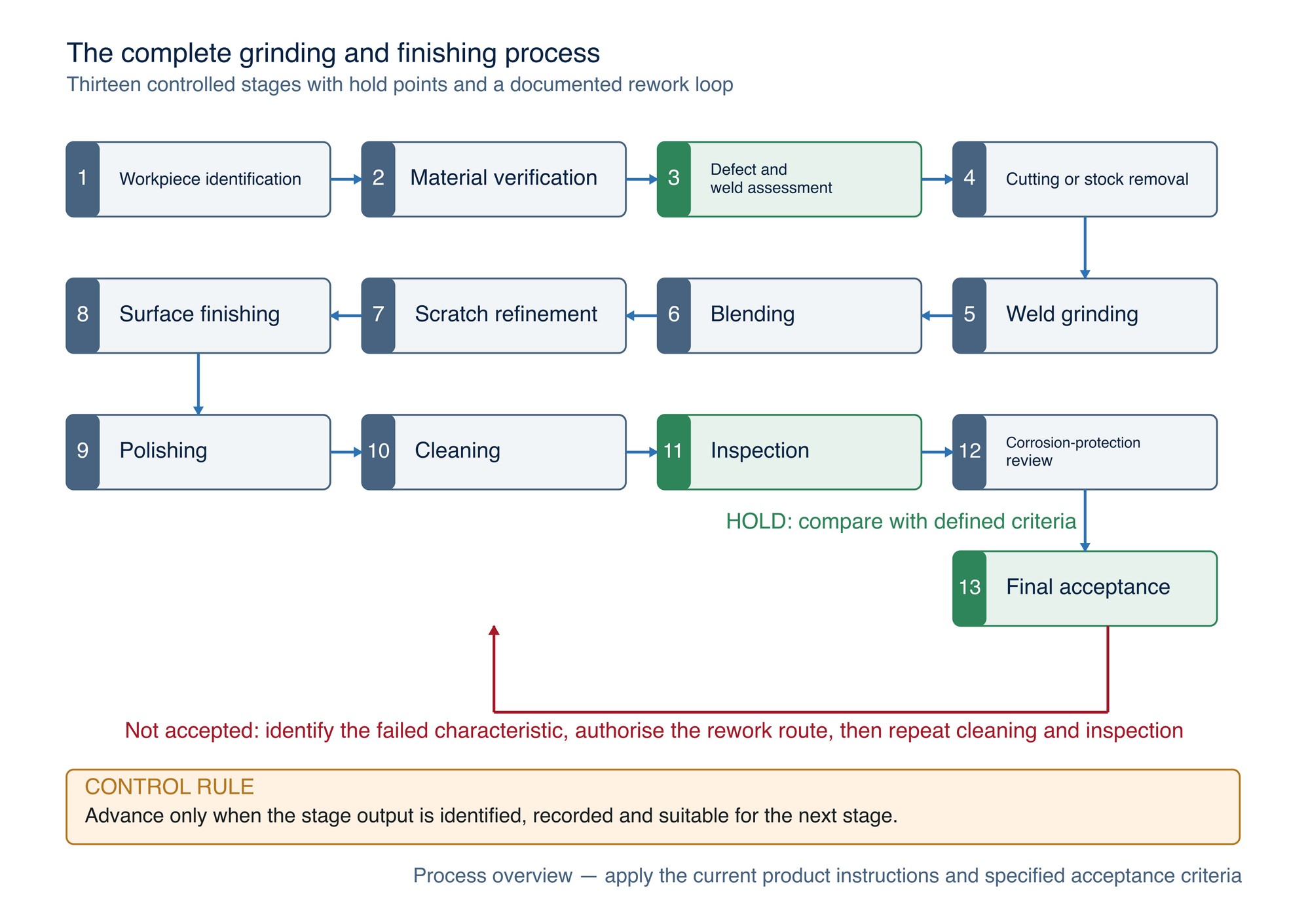
Manufacturer application guides commonly separate weld levelling, blending and final finishing rather than treating them as one operation. [S004; S006; S015] This chapter extends that principle into a complete factory workflow. The thirteen-stage map organises decisions, hold points and records while keeping product selection tied to the exact application.
The four control zones
The thirteen stages form four practical zones.
| Zone | Stages | Control question |
|---|---|---|
| Define | 1–3 | Do we know what the workpiece is, what condition it is in and what result is required? |
| Remove and shape | 4–6 | What material must be removed, and how will geometry be preserved? |
| Refine and restore | 7–10 | What scratch, appearance and cleanliness must be created without introducing a new defect? |
| Verify and release | 11–13 | Does the result meet every defined requirement, including corrosion-related requirements? |
Stage boundaries matter. If weld reinforcement remains above the approved profile, a fine finishing product is being asked to perform stock removal. If deep stock-removal scratches remain, polishing will make the surface brighter without necessarily removing them. If contamination remains after polishing, appearance alone cannot prove corrosion suitability.
Define acceptance before removing material
Grinding is usually irreversible. Before the first cut, identify the required geometry, finish, dimensional tolerance, corrosion condition, cleanliness, inspection method and authority for acceptance. The controlling requirement may come from a drawing, weld procedure, customer specification, approved visual comparator, surface-roughness requirement, hygiene requirement or engineering disposition.
Avoid descriptions such as “smooth,” “clean,” “polished” or “good enough” unless the workplace has translated them into an approved reference. A complete requirement might identify:
- the area that may be processed and any protected surface;
- whether weld reinforcement is to remain, be reduced or be made flush;
- the required edge radius, contour, flatness and dimensional minimum;
- direction and uniformity of the scratch pattern;
- permitted and prohibited visual features under defined lighting;
- measured surface-roughness requirement and measurement method, if applicable;
- removal of heat tint, embedded contamination or process residue;
- cleaning and corrosion-restoration method, if required; and
- inspection authority and required records.
Product-specific control — Select the abrasive and machine as a complete system. Confirm product-to-machine compatibility, operating limits and replacement criteria from current product information. Refer to the product label, Technical Data Sheet, or MKTECH representative.
The removal-to-finish hierarchy
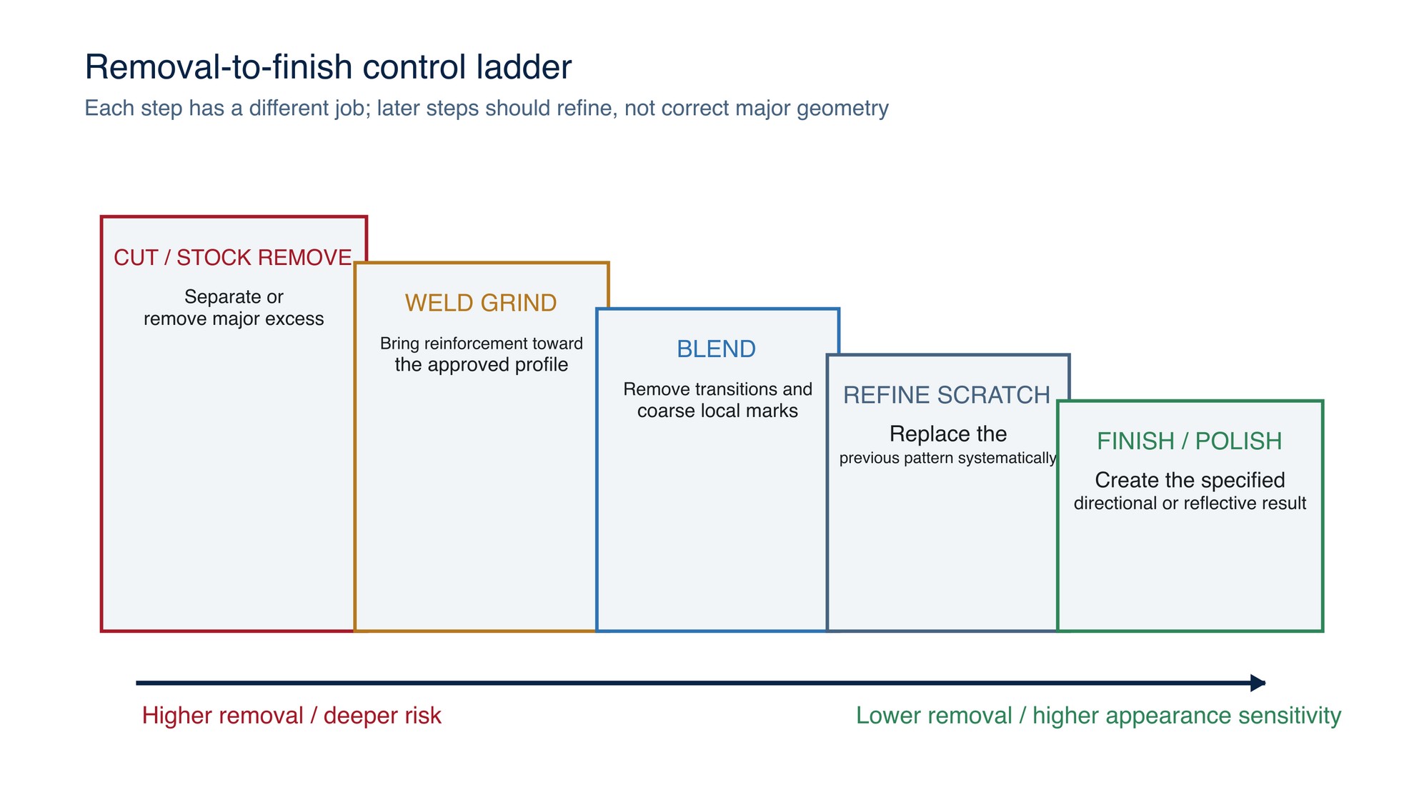
The stages between cutting and polishing do different jobs. Combining their names can hide the real cause of slow production or rework.
Cutting or stock removal
The purpose is separation or major reduction of excess material. The dominant risks are loss of dimension, heat, burrs, edge damage and an excessively deep starting scratch. The chosen system must suit the material, geometry and machine; a cutting product must never be used for side grinding unless its current instructions expressly permit it.
Weld grinding
The purpose is to reduce weld reinforcement toward an approved profile while protecting parent material. It is controlled geometry work. Operators need a visible or measurable stop reference and must avoid undercutting beside the weld, thinning the parent material or flattening a required contour.
Blending
The purpose is to remove abrupt transitions and make the repaired zone flow into the surrounding surface. Blending should widen control, not widen damage. A blend can look smooth yet fail because the component has become hollow, crowned, wavy or dimensionally thin.
Scratch refinement
The purpose is to replace the preceding scratch pattern with a finer, controlled pattern. Progress only after the deeper scratches are removed under suitable lighting and viewing direction. Skipping a required refinement stage often transfers the defect to the final finish, where correction becomes slower and more expensive.
Surface finishing and polishing
Surface finishing creates the specified directional, satin, matte or otherwise controlled texture. Polishing reduces visible scratch contrast and may build a reflective appearance. They are not synonyms, and polishing is not always required. Neither operation proves cleanliness, passivity or corrosion resistance.
Stage-by-stage controlled method
Stage 1 — Workpiece identification
Purpose: establish the identity, scope and traceability of the job before any irreversible action.
Record the component or batch number, drawing revision, customer or internal order, process area, initial photographs and any protected surfaces. Mark the exact weld, defect or zone to be processed using an approved method that will not contaminate or damage the material.
Confirm the process traveller accompanies the workpiece. If several similar components are present, use positive identification rather than location, memory or appearance. Quarantine any workpiece whose identity conflicts with its documents.
Output and hold condition: the physical workpiece and controlled documents agree; the permitted work area and required result are traceable.
Stage 2 — Material verification
Purpose: determine what material and surface state will actually be processed.
Verify material grade, thickness, heat or batch where required, coating or plating, cladding, hardness or heat-treatment state, and existing surface finish. Use the specified identification method. If positive material identification is required, record the instrument, method, result and operator. Do not infer stainless grade from colour, magnet response alone or the previous job.
Material verification also includes contamination risk. Separate tools and abrasives may be required for stainless steel, aluminium, titanium, nickel alloys or hygiene-sensitive work. Existing paint, oil, galvanising, thermal oxide, plating or unknown residue can change both process behaviour and exposure controls.
Stop condition: unidentified material, uncertain coating, unexpected thickness or conflicting certification.
Stage 3 — Defect and weld assessment
Purpose: decide whether grinding is permitted and define the removal boundary.
This is the first formal hold point. Assess the weld or defect before hiding evidence. Record location, length, width, depth, orientation and relationship to an edge, bend, hole, heat-affected zone or critical dimension. Use the approved examination method. Visual assessment may need to be supplemented by dimensional inspection or non-destructive testing.
Distinguish features that grinding may correct from conditions needing engineering or welding disposition. Cracks, suspected lack of fusion, repeated porosity, deep undercut, distortion, minimum-wall risk or an unexplained defect pattern must not be cosmetically blended away. Where repair welding is authorised, complete that route and repeat assessment before grinding.
Define the maximum permitted removal and the method for checking it. If no acceptance criterion exists, quarantine the workpiece and obtain one.
Release to removal: authorised assessor, defined removal boundary, confirmed remaining-section requirement and documented acceptance criteria.
Stage 4 — Cutting or stock removal
Purpose: separate the part or remove major excess efficiently while leaving controlled allowance for later stages.
Verify the machine, guard, mounting system, product identity, dimensions and maximum rated speed against current instructions before use. [S007; S018] Inspect the product and machine condition. Secure the workpiece and protect adjacent surfaces. Confirm spark, fire, dust, fume and noise controls from the workplace assessment. [S009; S014; S017]
Plan the cut or removal direction so that heat, burr, breakout and loss of support do not damage the component. Leave only the allowance needed for the next stage; excess allowance wastes time, while insufficient allowance can force the next stage to correct rough geometry. Mark and measure critical dimensions rather than relying on visual judgement.
Output: major excess removed, no unauthorised gouge or thermal damage, and adequate controlled allowance remains.
Stage 5 — Weld grinding
Purpose: bring weld reinforcement toward the specified profile without reducing parent material below its approved condition.
Work from the highest weld areas toward the stop reference. Maintain a supported, controlled contact area and a pass pattern appropriate to the product instructions. Avoid stationary dwell and repeated concentrated contact at thin edges.
Inspect frequently from more than one direction; a weld that appears flush from one angle may remain high or contain a hollow transition.
Use a template, straightedge, contour gauge, thickness method or other approved aid where geometry matters. Stop before the weld disappears into the parent surface if later blending still requires material. Do not use colour as a universal temperature measurement or acceptance criterion.
Output: reinforcement is within the blending allowance, critical geometry remains protected and no new crack-like mark, undercut, gouge or unacceptable heat tint is present.
Stage 6 — Blending
Purpose: remove the visible or tactile step between the processed zone and adjacent surface.
Blend over the smallest practical area that produces the specified transition. Follow the component geometry rather than forcing a flat tool path onto a curve. Cross-check profile using grazing light and a physical reference where permitted.
Maintain the defined scratch direction if the surrounding finish must be matched.
Blending is complete when the transition meets geometry requirements, not merely when the weld line becomes difficult to see. If the operator must keep expanding the blend zone to hide a dip, stop and assess the profile; continued blending can convert a local defect into widespread thinning.
Output: approved transition and contour with the parent material protected.
Stage 7 — Scratch refinement
Purpose: remove the unwanted scratch pattern from the previous stage and establish a controlled foundation for the final finish.
Clean loose debris between changes so that a coarse particle is not carried forward. Use consistent lighting and, where useful, change the direction of the next scratch pattern so remaining previous-stage marks can be distinguished. Advance only when the preceding scratch is removed throughout the complete process zone.
The correct sequence depends on starting condition, product construction, material, geometry, machine and required finish. Manufacturer application guides can illustrate staged combinations, but those combinations remain product-specific. [S004; S005; S006; S015]
Stop condition: isolated deep scratches, embedded particles, loading, smearing, unexpected heat tint or a finish zone that continues to grow.
Stage 8 — Surface finishing
Purpose: create the specified direction, texture, uniformity and boundary.
Define the finish direction before starting. Establish a controlled start and stop beyond the acceptance area where the design permits, or use an approved masking and feathering method. Overlap passes consistently and inspect for stripes, cross-scratches, swirls, edge rounding, patchiness and colour variation.
For an existing architectural or mill finish, prepare an approved comparator or representative trial coupon. A nominal abrasive grade alone does not define the resulting appearance; tool type, pressure, speed, wear, contact geometry and pass pattern also contribute.
Output: specified texture and direction across the defined area, ready for polishing if polishing is required.
Stage 9 — Polishing
Purpose: achieve an approved low-scratch or reflective appearance after geometry and refinement are already correct.
Confirm that polishing is required. Prepare a clean, controlled area and prevent transfer of compounds or particles between materials or polishing stages. Use the product and compound exactly within current instructions and workplace chemical controls. Inspect the surface under the specified lighting for haze, residual lines, drag marks, compound staining, waves and local overheating.
Polishing should not be used to conceal geometry, deep scratches or incomplete blending. It may increase reflectivity and make waviness more visible. If the target is a directional satin finish, polishing may be inappropriate.
Output: approved appearance without residue or concealed defects.
Stage 10 — Cleaning
Purpose: remove abrasive debris, loose metal, polishing compound, oil, fingerprints, marking residue and other process contamination before inspection.
Cleaning is a process stage, not housekeeping after acceptance. Select the method for the material, contamination and service requirement. Use identified chemicals with current safety data, approved dilution and contact controls, suitable rinsing and complete drying. The Malaysian chemical-control framework requires assessment and control of hazardous chemical exposure; local exhaust is one recognised engineering-control context for applicable grinding operations. [S009; S017]
Use clean tools and wipes suitable for the material. Prevent recontamination from carbon-steel benches, dirty gloves, shared brushes, shop dust, chloride-containing cleaners or uncontrolled water quality. Cleaning must not erase identification or introduce a new finish difference.
Output: dry, residue-free surface suitable for reliable inspection and corrosion-protection review.
Stage 11 — Inspection
Purpose: compare the cleaned result with every defined acceptance criterion.
This is the second formal hold point. Inspect identity, dimensions, contour, remaining thickness where required, finish direction, visual uniformity, scratches, burrs, heat tint, cleanliness and any specified roughness or non-destructive test result.
Use the required lighting, viewing distance, comparator, instrument and calibration status. Record the result rather than relying on an untraceable verbal release.
Inspect the full affected zone, including transition edges and the reverse side where heat, distortion or breakthrough could appear. Separate observations from decisions: first record what is present; then compare it with the controlled criterion.
Decision: pass to corrosion-protection review, or identify the precise failed characteristic and initiate an authorised rework or rejection route.
Stage 12 — Corrosion-protection review
Purpose: determine whether mechanical appearance and cleaning are sufficient for the alloy and intended service, or whether an approved restoration treatment is required.
Stainless-steel heat tint and iron contamination can require attention beyond cosmetic finishing. Pickling and passivation are distinct chemical surface treatments, and their need depends on material, fabrication history, contamination, service and specification. [S001; S016] Do not claim that a bright or uniform surface is automatically passive or corrosion-ready.
The authorised engineering or quality function should review heat tint, embedded contamination, free-iron control, chemical cleaning or passivation requirements, rinse-water and waste controls, verification method and service environment.
Chemical restoration must follow an approved procedure, current technical and safety data, and the workplace chemical assessment. If treatment changes the appearance or condition, repeat the required cleaning and inspection.
Output: documented determination that corrosion-related requirements are satisfied or a controlled treatment and reinspection route is defined.
Stage 13 — Final acceptance
Purpose: release only a workpiece that meets the complete requirement and has a complete record.
The authorised acceptor verifies that all hold points are signed, deviations are resolved, required treatment and inspection records are attached, identification remains intact and the workpiece is protected for storage or the next operation.
Acceptance is not the absence of a visible complaint; it is a positive, traceable decision against defined criteria.
Photograph the accepted surface when the procedure requires it. Protect the finish from handling damage, condensation, cross-contamination and unsuitable packaging. Transfer any storage, transport or installation restrictions with the workpiece.
Final output: accepted component, complete process traveller, recorded approver and controlled status.
The authorised rework loop
A failed inspection does not automatically justify repeating the last abrasive operation. Record the failed characteristic and determine the earliest stage capable of correcting it without violating dimensional or material limits.
| Failed characteristic | Possible return point | Required check before rework |
|---|---|---|
| Excess weld reinforcement | Stage 5 | Remaining material and weld-repair disposition |
| Hollow or abrupt transition | Stage 3 or 6 | Geometry, remaining thickness and engineering authority |
| Coarse scratch remains | Stage 7 | Scratch source, contamination and refinement route |
| Non-uniform directional finish | Stage 8 | Finish reference, boundary and remaining allowance |
| Polishing haze or compound mark | Stage 9 or 10 | Cleanliness, compound compatibility and finish target |
| Contamination or residue | Stage 10 | Contaminant identity and approved cleaning method |
| Heat tint or corrosion concern | Stage 3 or 12 | Alloy, service, acceptance and restoration route |
After any abrasive or chemical rework, repeat cleaning, inspection and the corrosion-protection review. Record the rework cycle, changed variables and remaining dimensional margin. Escalate repeated failure; more passes are not a process-improvement method.
Process traveller — minimum record
| Section | Required record |
|---|---|
| Job identity | Component/batch ID, drawing and revision, order, area to process |
| Material | Grade, thickness, certification or identification method, coating and initial finish |
| Assessment | Defect/weld description, measurements, photographs, removal boundary and authorisation |
| Requirement | Geometry, finish, cleanliness, corrosion and inspection criteria |
| Equipment | Machine ID, guard, mounting system, speed setting where applicable, condition check |
| Consumable | Manufacturer, full product/SKU, size, grade/grit, batch where required, rated-speed check |
| Method | Stage, sequence, pass direction, process boundary and replacement rule |
| Controls | Workholding, dust/fume, chemical, fire/spark, noise, contamination and PPE controls |
| Result | Measurements, visual comparison, test results, photographs and rework history |
| Release | Inspector, corrosion review, final approver, date and status |
Application example — stainless enclosure
A fabricated stainless enclosure has a welded external corner that must visually match the specified directional reference while retaining the required corner profile. The example shows how to organise the operation without assigning an unverified abrasive specification.
- The traveller links the enclosure serial number to the current drawing and marks the permitted process zone.
- Material certificate and thickness are confirmed; the surface is checked for protective film, oil and carbon-steel contamination.
- The weld is examined before grinding. The assessor records reinforcement, undercut status, corner geometry and minimum remaining thickness.
- Major excess is reduced only if required, leaving allowance for controlled weld grinding.
- The weld is brought toward the approved corner profile using the verified machine-product system.
- The transition is blended without flattening the corner.
- Coarse scratches are replaced through the trial-approved refinement sequence.
- The directional finish is recreated across the authorised zone using the reference comparator.
- Polishing is omitted because the specified result is directional, not reflective.
- The enclosure is cleaned with the approved material-compatible method and dried.
- QA checks profile, finish direction, scratch uniformity, heat tint, cleanliness and relevant dimensions.
- Engineering confirms the approved fabrication-cleaning route satisfies the corrosion requirement for the intended service.
- QA records acceptance and the surface is protected for packing.
The example shows why “grind and polish the weld” is an inadequate instruction. It omits identification, assessment, geometry, contamination, finish reference, corrosion review and release authority.
Factory process checklist
Before removal
- [ ] Workpiece and current documents agree.
- [ ] Material, thickness, coating and initial finish are verified.
- [ ] Defect or weld has been assessed before evidence is removed.
- [ ] Permitted removal, protected surfaces and acceptance criteria are defined.
- [ ] Machine, guard, mounting, product and rated-speed compatibility are verified.
- [ ] Workholding and exposure, spark, fire, noise and contamination controls are in place.
During removal and refinement
- [ ] Each product is performing the intended stage rather than compensating for a skipped stage.
- [ ] Geometry and remaining material are checked before the visual stop point is exceeded.
- [ ] Abrasive condition, loading, vibration, heat tint and scratch pattern are monitored.
- [ ] Loose debris and cross-contamination are controlled between stages.
- [ ] Process changes and abnormal observations are recorded.
Before release
- [ ] The surface is cleaned and dry before inspection.
- [ ] All dimensional, profile, finish, roughness, cleanliness and test criteria are checked as applicable.
- [ ] Corrosion-protection requirements have been reviewed by the authorised function.
- [ ] Any rework returned through a documented stage and was reinspected.
- [ ] Final acceptance is signed and the finished surface is protected.
Key takeaways
- Define the workpiece, material, defect and acceptance requirement before removing material.
- Cutting, weld grinding, blending, scratch refinement, finishing and polishing are separate jobs.
- A later, finer stage should not be used to correct major geometry or deep uncontrolled scratches.
- Cleaning, inspection and corrosion-protection review are independent of cosmetic appearance.
- Failed inspection requires an authorised return point, not automatic repeated grinding.
- Final acceptance must be positive, traceable and based on the complete requirement.
- Product-specific sequences and operating limits must be taken from current product information and confirmed on representative work.
Applying the process to a product
For each operation, match the exact abrasive to the material, machine, mounting system, dimensions and intended action. Establish the required finish with a drawing, measurable criterion or approved physical comparator, then confirm the sequence on representative material before repeat work.
Cleaning, passivation and corrosion-restoration treatments must be compatible with the alloy and intended service. Use current chemical information, the workplace chemical assessment and the specified inspection method. Refer to the product label, Technical Data Sheet, or MKTECH representative.
Understanding Industrial Materials
The “Understanding Industrial Materials” section begins on the following page of the printed handbook (page 20), outside this chapter extract.