
Production engineers, supervisors, operators, QA/QC personnel, maintenance teams, safety personnel, procurement staff and technical sales personnel
A verification-first guide to predicting material response during cutting, grinding, blending, finishing and polishing. It does not provide universal product, grit, pressure, angle or speed recommendations.
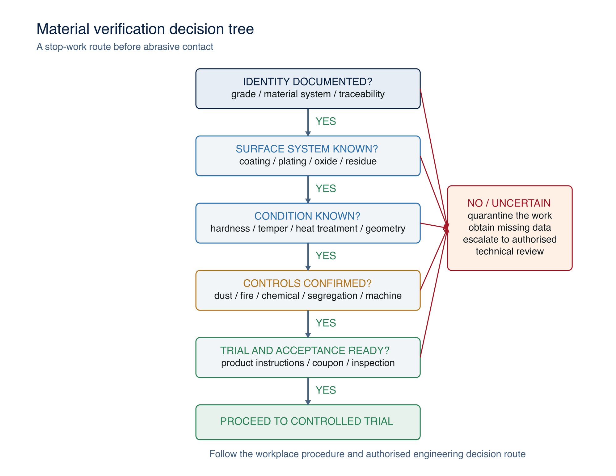
A material name is not a safe operating instruction. Before abrasive contact, verify the alloy or material system, heat-treatment or hardness condition, coating, contamination controls, dust and fire characteristics, machine and abrasive compatibility, current product instructions and workplace risk assessment. Stop when any material, coating or composite constituent is unknown. [S009; S014; S017; S018; S020; S022; S026]
Chapter objectives
After this chapter, the reader should be able to:
- distinguish material family from verified grade, condition and surface system;
- explain how heat, work hardening, loading, smearing, scratching, burrs and contamination develop;
- anticipate different responses from mild steel, carbon steel, stainless steel, aluminium, cast iron, tool steel, galvanised steel, other non-ferrous metals, coated surfaces and composites;
- identify when a material-specific tool, dust control, cleaning route or coating repair is required;
- set a controlled trial without inventing a universal cutting speed or grit sequence; and
- recognise when product identity or application conditions require confirmation before use.
The material label is only the first input
Industrial materials cannot be selected or processed reliably from colour, magnet response, weight or a broad description such as “steel” or “aluminium.” Within one family, alloy content, manufacturing route, heat treatment, hardness, cold work, casting structure, coating and previous processing can change how a surface cuts and how it fails.
Established machinability classifications separate steels, stainless steels, cast irons, non-ferrous metals, heat-resistant alloys and hardened materials because each group presents different cutting characteristics. They subdivide those groups because material family alone does not provide enough information for process selection. [S019] Abrasive work demands the same discipline: group-level behaviour helps form a hypothesis, but grade and condition must control the trial.
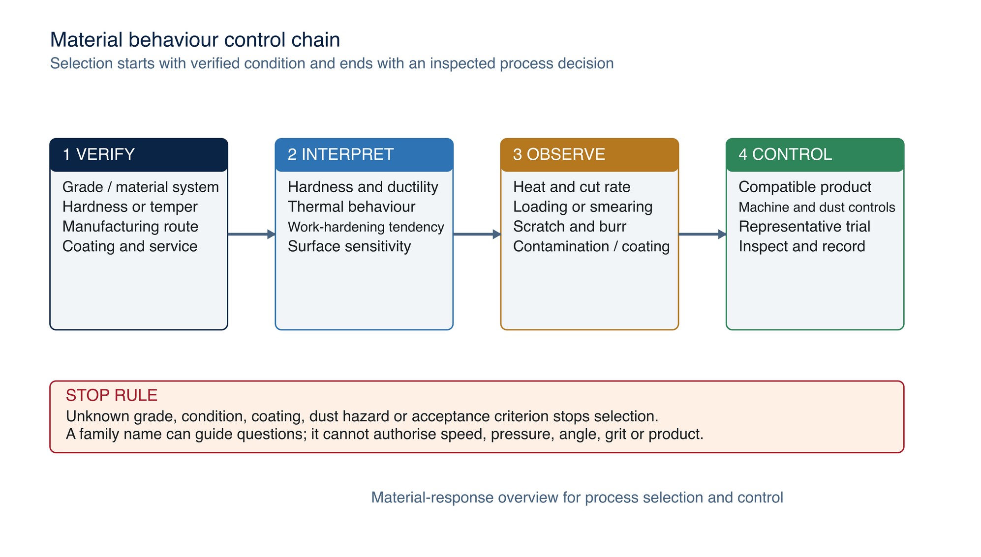
Minimum material record before selection
- material family and verified grade or specification;
- thickness, geometry and critical dimensions;
- heat treatment, hardness, temper or cold-worked condition where relevant;
- manufacturing route, including rolled, forged, cast, powder-metallurgy or composite construction;
- coating, plating, cladding, conversion layer, paint, oxide or unknown residue;
- required final texture, direction, roughness, gloss, coating condition or corrosion performance;
- service sensitivity, including food, pharmaceutical, marine, high-temperature or fatigue-critical use; and
- contamination, dust, fire, chemical and waste-control requirements.
If the material identity or condition is uncertain, do not select solely on a “general-purpose” description. Confirm the work material and starting condition, then compare suitable product families on representative work.
What the operator actually observes
Heat generation
Grinding converts mechanical work into heat at the contact. The temperature pattern depends on speed, pressure, contact area, duration, abrasive sharpness, loading, workpiece thermal properties, geometry and cooling conditions. OSHA's archived aluminium guidance specifically notes that heat cannot be reduced to a single amount because process speed, composition, contact area, duration and pressure all matter. [S020] Treat colour, touch and spark appearance as observations, not universal temperature measurements.
Heat may soften a coating, distort a thin section, temper a hardened steel, accelerate loading, produce stainless heat tint, degrade a composite resin or create a fire and dust-control problem. Control begins by limiting unnecessary dwell and by choosing a product and process proven for the verified material.
Work hardening
Work hardening is local strengthening caused by plastic deformation. Austenitic stainless steels and some nickel or titanium alloys can harden at the worked surface. [S003; S019] If an abrasive rubs instead of cutting, the next pass may encounter a harder skin, increasing force and heat. A sharp, stable cutting action and frequent inspection are therefore more important than continuing with extra pressure.
Do not describe every hard-to-grind surface as work hardened. A hard heat treatment, hard oxide, embedded grit, glazing, abrasive loading or loss of tool support can create similar symptoms. Verify the cause before changing the process.
Loading and glazing
Loading occurs when removed material or residue packs into the working surface of an abrasive. Glazing occurs when active cutting points become dull or ineffective while the product continues to rub. Ductile or adhesive materials can promote loading; excessive heat, unsuitable pressure, a closed product structure or contamination can worsen it. The practical signs are reduced cut, increased force, surface drag, streaks, heat and transferred material.
Replacing pressure with evidence is the key control. Stop, inspect the abrasive and surface, identify whether the product may be cleaned or dressed under its instructions, and verify that its construction is intended for the material. Never improvise cleaning, lubrication or dressing on a product whose instructions do not permit it.
Smearing and transfer
Smearing is displaced material spread across the surface rather than cleanly removed. It can conceal graphite in cast iron, close or drag a soft non-ferrous surface, cover a defect or redistribute contamination. Cast-iron preparation and machinability references identify matrix smearing, graphite pull-out and adhesive material flow as distinct process concerns. [S019; S024]
Smearing can make a surface look uniform while leaving a mechanically damaged layer. Inspect under directional light and, where necessary, use magnification, cleaning, metallography or another approved method rather than appearance alone.
Scratch formation
Every abrasive creates a distribution of scratches. Depth and uniformity depend on grain size and shape, backing or bond, contact geometry, force, speed, product condition, loose contamination and the workpiece response. A single hard particle carried forward can create a scratch much deeper than the intended stage.
Scratch refinement must therefore be verified, not assumed from the printed grit. Clean between stages, control direction, use suitable lighting and advance only when the unwanted preceding pattern has been removed.
Burr formation and edge change
Ductile materials tend to displace and form burrs; brittle materials may chip, fracture or break out. Burr shape changes with alloy, hardness, edge support, approach direction and tool condition. A burr is not only a sharpness problem: it can change dimension, interfere with assembly, retain contamination or indicate that the process is rubbing and pushing material.
Define the acceptable edge condition before grinding. A requirement to “remove the burr” must not become permission to remove a designed radius, chamfer, coating or minimum section.
Contamination
Particles transferred from tools, benches, brushes, dust collectors, gloves, compounds or another workpiece can change corrosion, appearance, coating adhesion or fire risk. Stainless steel may require stainless-only controls to prevent embedded iron. Aluminium dust mixed with iron oxide can contribute to a thermic reaction; OSHA's archived guidance recommends material-specific tools as one safeguard in that context. [S001; S020]
Segregation is a controlled system, not a coloured label alone. It includes storage, identification, cleaning, extraction, workholding, consumables and records.
Material-family response guide
The following profiles describe likely behaviour and the questions to ask. They do not replace grade-specific data or a representative trial.
Mild steel
“Mild steel” normally indicates low-carbon steel, but it is not a complete grade designation. Low-carbon steels can be ductile and may produce adhesive transfer or built-up material during cutting; scale, rust, weld metal and coatings can behave very differently from the base metal. Steel machinability changes with carbon content, hardness, heat treatment, alloying and manufacturing route. [S019]
Likely process observations
- burrs and edge rollover when the process pushes rather than cuts;
- loading or transferred material on some products and low-carbon conditions;
- sparks and scale debris that can obscure the true surface;
- deep scratches if heavy removal is allowed to define the final finish; and
- rapid visual brightening that does not prove rust, scale or a coating has been uniformly removed.
Control response
Verify the grade, scale, coating and weld condition. Select the product for the actual operation—cutting, weld reduction, blending or finishing—and define the dimensional stop. Keep carbon-steel tools and dust away from contamination-sensitive stainless, aluminium and non-ferrous work.
Carbon steel
Carbon steel spans a wide range. Increasing carbon content and hardening can increase hardness and abrasive resistance; carbide-forming alloy additions and heat treatment can further change the response. [S019] Treat “carbon steel” as a family requiring grade and hardness confirmation.
Likely process observations
- a soft or annealed condition may cut readily and form burrs;
- a hardened or tempered condition may cut slowly, generate concentrated heat and wear the abrasive rapidly;
- overheating can change the surface condition of heat-treated parts even when the geometry looks acceptable; and
- the same visual finish can hide different remaining hardness or thermal damage.
Control response
Record hardness or heat-treatment state when function depends on it. For springs, shafts, gears, blades, dies and other treated parts, define the permitted stock removal and thermal acceptance before work. Stop on unexpected colour, cracking, soft spots, rapid abrasive wear or a sudden change in cut.
Stainless steel
Stainless steel includes ferritic, martensitic, austenitic and duplex families. Austenitic grades can have high work-hardening rates and relatively low thermal conductivity compared with common carbon steels. [S003; S019] Grinding heat can create oxide colour; carbon-steel contamination can reduce corrosion performance; a bright finish does not prove passivity. [S001; S016]
Likely process observations
- concentrated heat and heat tint, especially on thin edges or with dwell;
- rising force if rubbing work-hardens the surface;
- loading, smearing or drag marks on an unsuitable product;
- directional scratches that become more visible as reflectivity increases; and
- embedded iron or dirty compound affecting corrosion-related acceptance.
Control response
Verify stainless family and grade, use the required stainless-only segregation, maintain a cutting rather than rubbing action and inspect heat tint and contamination separately from appearance. Any pickling, passivation or chemical restoration must follow an approved procedure; mechanical brightness alone is not release evidence.
Aluminium
Aluminium alloys are not one material. Strength, silicon content, temper, casting structure and coating alter their response. Many aluminium, copper and brass alloys are comparatively soft, while aluminium with higher silicon content can be abrasive. [S019]
Likely process observations
- rapid loading, smearing and surface transfer on unsuitable abrasives;
- burrs and feathered edges from ductile displacement;
- embedded coarse particles producing conspicuous scratches;
- local heat affecting thin sections, coatings or temper-sensitive parts; and
- fine aluminium dust creating a combustible-metal hazard under relevant conditions. [S020]
Control response
Use only abrasives, extraction and cleaning methods approved for the alloy and operation. Separate aluminium grinding from ferrous dust and contaminated tools. Do not assume “non-sparking” means no fire hazard. Assess combustible dust, thermic-reaction, hot-work and waste issues through the workplace risk assessment.
Cast iron
Cast iron behaviour depends on graphite form, matrix and hardness. Grey, ductile, compacted-graphite, malleable, white and austempered irons cannot be treated as one surface. Some graphitic irons machine comparatively readily, while hard white or austempered conditions can be substantially more demanding. [S019]
Likely process observations
- short, dusty debris rather than a long ductile burr on many graphitic grades;
- graphite pull-out, edge breakout or matrix smearing;
- hard chilled zones, carbides, casting skin, sand or inclusions causing abrupt changes in cut;
- a dark or apparently smooth surface concealing smeared matrix; and
- rapid flash staining or corrosion on freshly prepared surfaces in some conditions. [S024]
Control response
Confirm cast-iron type and hard spots before selecting the abrasive. Use dust controls suited to the casting and any residual sand or coating. If graphite integrity or metallurgical acceptance matters, process and inspect using the approved metallographic procedure rather than an appearance-only shop finish.
Tool steel and hardened steel
Tool steels may contain hard carbides and may be supplied annealed, pre-hardened, through-hardened, case-hardened or surface treated. Hardened steel requires separate process consideration because hardness increases heat, force and abrasive demand. [S019]
Likely process observations
- slower cut and rapid abrasive wear on hard grades;
- local overheating, temper colour, cracking or grinding burn;
- persistent deep scratches from an overly aggressive first stage;
- difficulty removing the disturbed layer before polishing; and
- orange peel, pitting or other poor finish from unsuitable or excessive polishing in some mould steels. [S023]
Control response
Verify grade, hardness, heat treatment, case depth, surface treatment and final function. Use small, verified refinement steps where high finish is required. Do not polish through a hard layer or use visual gloss as proof that the tool retains its specified hardness and geometry.
Galvanised steel
Galvanised steel is a steel substrate with a zinc coating. Grinding can change both profile and corrosion protection. The American Galvanizers Association advises minimising field fabrication that removes coating and repairing bare areas under the governing specification. [S021]
Likely process observations
- coating removal revealing a different-coloured substrate;
- zinc loading, smearing or debris on the abrasive;
- local thinning around edges and welds;
- an apparently blended area that no longer has the specified coating; and
- dust or fume requiring material-specific exposure controls.
Control response
Identify the galvanising specification, original coating condition, permitted repair area and approved repair method before grinding. Mark the minimum process zone. Inspect both smoothness and remaining or restored coating. Do not accept bare steel because the repair looks cosmetically uniform.
Other non-ferrous metals
“Non-ferrous” includes copper and copper alloys, nickel alloys, titanium, magnesium, zinc and many others. Their behaviour ranges from soft and adhesive to work-hardening, heat-concentrating or combustible. Common machining classifications group aluminium, copper and brass separately from nickel-based heat-resistant alloys and titanium because work hardening, adhesion and heat behaviour differ materially. [S019]
Likely process observations
- copper and some soft alloys may load, smear and form heavy burrs;
- nickel alloys may work harden and retain heat at the cutting zone;
- titanium may gall, concentrate heat and react with unsuitable process conditions;
- magnesium, aluminium and titanium fines can require combustible-metal controls; and
- each alloy can impose different contamination, coolant and surface-cleanliness requirements.
Control response
Never select from the word “non-ferrous” alone. Identify the alloy and service, obtain current manufacturer guidance and determine fire, dust, extraction and cross-contamination controls before the trial.
Coated surfaces
A coated surface is a material system: substrate, preparation layer, primer, conversion coating, plating, paint, thermal spray or other layer may each have a function. Abrasive work can release hazardous constituents, change adhesion, expose the substrate or make the original specification impossible to verify. HSE documentation shows that sanding or grinding chromium-VI-treated surfaces can create inhalation exposure in relevant uses. [S026]
Likely process observations
- coating softening, melting, loading or feathering;
- dust colour or odour that is not a reliable identification method;
- breakthrough at peaks, edges or welds before the full area looks clean;
- loss of corrosion protection, electrical insulation, friction or adhesion function; and
- mixed dust containing coating, corrosion product, substrate and abrasive.
Control response
Stop on every unknown coating. Obtain the coating specification, safety data and removal or repair procedure. Define whether the task is cleaning, keying, stripping, feathering or defect repair. Control exposure and waste under the Malaysian chemical framework. [S009; S017] Inspect the required remaining profile, clean boundary and restored coating—not only appearance.
Composite materials
Composites combine a matrix with fibres, particles, cores, skins, adhesives or coatings. Glass-fibre, carbon-fibre and aramid systems respond differently, and thermoset and thermoplastic matrices behave differently under heat. NIOSH testing demonstrates that sanding carbon-fibre-reinforced nanocomposites can release fibres and particles; the measured emission depends on the tested panel and process. [S022]
Likely process observations
- resin heating, glazing, melting or smearing;
- fibre fraying, pull-out, delamination or exposed core;
- dust with fibre, resin, filler and coating constituents;
- electrical or equipment contamination from conductive carbon-fibre dust; and
- a smooth surface concealing subsurface delamination or heat damage.
Control response
Process composites only under a material-specific procedure. Verify lay-up, fibre and resin system, thickness, repair limits, dust capture, cleaning and inspection method. Use the approved cutting or sanding product and support. Stop on discolouration, odour, softening, fibre breakout, delamination or uncertain dust control.
The product-selection logic
Product selection is an engineering match between the verified material system and the required operation. It is not a lookup from one material name.
-
Step 1 — Verify identity and condition
Confirm grade, hardness or temper, coating, manufacturing route, initial surface and prior repair. Resolve conflicts between marking, certificate, drawing and physical condition.
-
Step 2 — Define the required change
Separate stock removal, weld reduction, burr removal, coating preparation, scratch refinement and final finishing. Each has a different removal rate, contact geometry and acceptance method.
-
Step 3 — Identify the dominant failure risks
Select from heat, work hardening, loading, smearing, burrs, edge breakout, contamination, coating loss, dust, fire, distortion, grinding burn and appearance mismatch. Rank the risks for the actual component.
-
Step 4 — Verify machine and product compatibility
Use the current machine and abrasive instructions. Confirm dimensions, mounting, guard, permitted use, maximum rated speed, support, direction and condition. [S007; S018] Product-specific operating speed, angle, force, lubrication and replacement rules must come from the identified current data—not this chapter.
-
Step 5 — Establish a controlled trial
Use a representative coupon or approved non-critical zone where possible. Record material, product, machine, speed setting, contact method, time, wear, loading, temperature-control observations, scratch result, burr and cleaning outcome. Change one meaningful variable at a time.
-
Step 6 — Inspect against function
Compare geometry, finish, coating, cleanliness and material condition with the controlled requirement. A faster cut is not an improvement if it creates a deeper scratch, wider heat-affected zone, coating breakthrough, contamination or rework.
Cutting speed is controlled, not guessed
Surface speed influences cutting action, heat, wear, loading and finish, but the safe and effective range depends on the product, machine, diameter, material and operation. There is no universal “steel speed,” “aluminium speed” or “stainless speed.”
The operator must distinguish three different limits:
- the machine's available and selected speed;
- the abrasive product's maximum permitted speed and application range; and
- the validated process setting for the verified material and required result.
Never treat the maximum rated speed as the recommended process speed, and never exceed it. Set the machine only within the declared range for the complete machine-product combination. Refer to the product label, Technical Data Sheet, or MKTECH representative.
Appearance is evidence only when the criterion defines it
Materials create different visual signals: steel sparks, stainless heat tint, aluminium drag marks, cast-iron darkening, zinc breakthrough, coating feather edges and composite fibre exposure. These signals help diagnosis but do not by themselves prove acceptance.
| Visible observation | Possible meaning | Required confirmation |
|---|---|---|
| Cut rate falls while force rises | Loading, glazing, work-hardened skin or harder local structure | Inspect product and surface; verify material condition and product suitability |
| Surface becomes shiny but lines remain | Smearing or polishing over a deeper scratch | Clean and inspect under directional light; verify previous pattern removal |
| Blue, straw or dark colour on metal | Oxide or thermal effect | Material-specific acceptance; do not infer a universal temperature |
| Dark cast-iron surface | Graphite, smear, oxide or debris | Clean and use approved magnification or metallographic method if required |
| Bright steel visible through zinc or paint | Coating breakthrough | Measure or inspect against coating-repair specification |
| Frayed or pale composite edge | Fibre breakout, resin removal or delamination | Stop and use approved composite inspection method |
Contamination-control minimum
- identify and segregate tools, abrasives, compounds, brushes and wipes where the procedure requires it;
- clean workholding, benches and extraction systems before contamination-sensitive work;
- prevent ferrous dust entering aluminium or combustible-metal collection routes;
- prevent carbon-steel particles embedding in stainless surfaces;
- prevent coarse abrasive or polishing compound carrying into a finer stage;
- label material-specific consumables and quarantine any whose history is uncertain; and
- record cleaning and segregation checks on the process traveller.
Illustrative factory example
Application example — material identity controls selection. A fabrication cell receives three visually similar parts: low-carbon steel, austenitic stainless steel and aluminium alloy. Each requires removal of a small weld transition and a uniform directional finish.
The team does not apply one disc and one speed to all three. It first confirms identity and finish criteria. The steel route focuses on burr, geometry and scale; the stainless route adds heat-tint and iron-contamination controls; the aluminium route uses a material-approved product and segregated dust-control route because loading, smearing and combustible dust are credible concerns. Each route is trialled and recorded separately. The final finishes may look similarly uniform, but the control evidence is different.
Pre-process material checklist
- [ ] Workpiece identity agrees with the drawing, certificate or approved identification method.
- [ ] Grade, condition, thickness and critical dimensions are recorded.
- [ ] Heat treatment, hardness, temper or cold work is known where relevant.
- [ ] Coating, plating, oxide, paint, cladding or residue is identified.
- [ ] Required geometry, texture, roughness, gloss, coating and corrosion condition are defined.
- [ ] Dust, fire, chemical, noise, vibration and waste controls are approved.
- [ ] Contamination segregation and cleaning controls are ready.
- [ ] Machine, guard, mounting and abrasive rated-speed compatibility are verified.
- [ ] Product application instructions cover the material and operation.
- [ ] A representative trial and inspection method are authorised.
- [ ] Stop conditions and technical escalation contact are known.
Applying product information to the material
Confirm the exact abrasive declaration against the verified material, coating, hardness or heat-treatment condition and the intended operation. Check machine compatibility, working method, permitted coolant or lubricant use, and any special handling or extraction requirements before use.
Compare candidate products on representative work using consistent geometry, contact method and inspection. Judge the complete result: removal, heat, loading, edge condition, dimensional control, surface finish and downstream suitability.
Refer to the product label, Technical Data Sheet, or MKTECH representative.
Source-code key
Every [Sxxx] citation in this chapter resolves in the Complete source index at the end of the handbook. Source codes identify the publication supporting the stated principle and do not create an MKTECH product specification.
Stainless-Steel Behaviour During Grinding
The stainless-steel behaviour table appears on the following page of the printed handbook (page 29), outside this chapter extract.