
Production engineers, supervisors, operators, QA/QC personnel, maintenance teams, safety personnel, procurement staff and technical sales personnel
Stainless-steel behaviour during cutting, grinding, blending and finishing. This chapter explains control logic but does not establish an MKTECH product sequence, universal grit, operating speed, pressure, angle or chemical procedure.
Verify the stainless grade, condition, service duty, required finish, contamination controls, machine and abrasive compatibility, dust controls and approved cleaning route before abrasive contact. Stop when the alloy, coating, contamination status, acceptance criterion or chemical procedure is unknown. [S001; S009; S014; S017; S018; S027]
Chapter objectives
After this chapter, the reader should be able to:
- explain the function and limitations of the chromium-rich passive surface;
- recognise how thermal behaviour and work hardening change the grinding response;
- distinguish heat tint, smearing, embedded iron and ordinary surface soil;
- prevent contamination through stainless-only tools, media, storage and work areas;
- define a controlled before-and-after inspection rather than judging by brightness alone; and
- route cleaning, pickling or passivation to an approved procedure.
Stainless is a material system, not a cosmetic finish
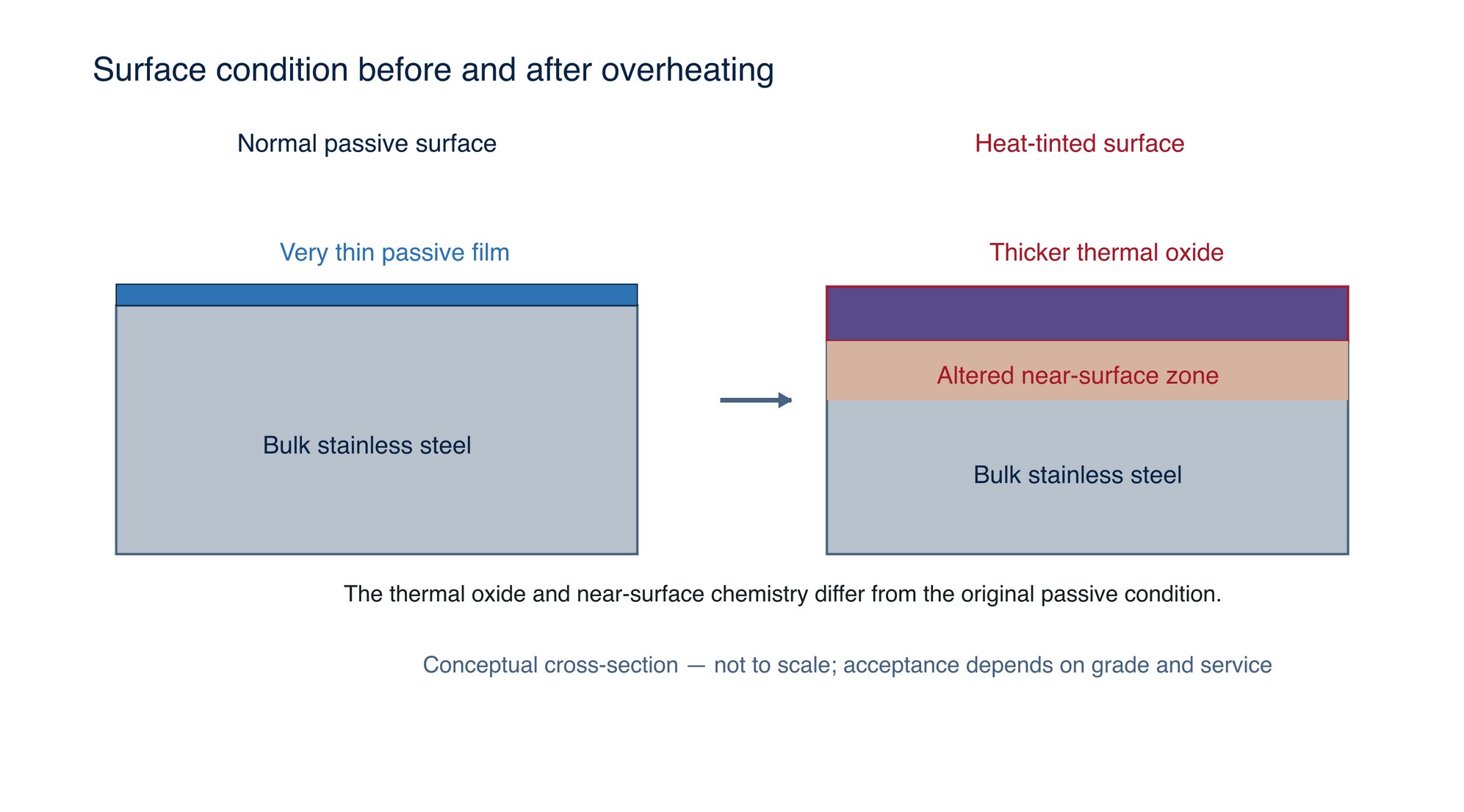
Stainless steel is corrosion resistant because alloying and a clean, oxygen-exposed surface support a thin chromium-rich passive film. The film is not paint, and it is not immune to damage. Heat tint, embedded iron, scale, chloride-bearing deposits, unsuitable chemicals, rough damaged areas and poor cleaning can interfere with the intended surface condition.
Worldstainless and BSSA both emphasise cleanliness and the continuous passive condition. [S001; S016; S027]
Grinding can change several things at once: geometry, roughness, scratch direction, residual contamination, oxide condition and local strain. A bright surface may therefore be visually improved but technically unacceptable. The operator must know which function is being restored: dimension, weld profile, directional finish, cleanability, passive-surface readiness or appearance.
Minimum job record
- verified grade and product form;
- heat-treatment or cold-worked condition where relevant;
- thickness, geometry, weld condition and distortion limit;
- service environment and corrosion-critical zones;
- required finish, direction, comparator and measurable criterion;
- permitted cleaning, pickling, passivation and rinsing route;
- stainless-only zoning, tools, extraction and handling controls; and
- inspection and release authority.
If these inputs are incomplete, quarantine the work or establish an authorised trial on a representative coupon. Do not invent a finish from a grit number or a product name.
Why stainless behaves differently under an abrasive
Thermal conductivity and local heat
Many common austenitic stainless grades conduct heat less readily than carbon steel and can expand more for a given temperature rise. Grade-specific Outokumpu data show these differences, but the magnitude varies by alloy and temperature. [S003] During grinding, local heat is also controlled by product sharpness, loading, contact area, speed, force, dwell, support, thickness and cooling. A thin sheet, edge or weld transition can heat and distort rapidly even when the surrounding component remains cool.
The operator should watch the trend: falling cut rate, rising force, increased drag, concentrated tint, softened backing, waviness or loss of flatness. These signs trigger inspection; they are not temperature measurements.
Work hardening
Austenitic stainless steels are characterised by strong work hardening. [S003] When an abrasive cuts cleanly, it removes material. When it rubs, ploughs or dwells, it can deform the surface and leave the next pass confronting a harder local layer. The usual reaction—more pressure—can increase rubbing, heat and distortion.
Work hardening is not the only explanation for a difficult cut. A loaded or glazed abrasive, hard weld deposit, scale, local cold work, loss of support or an incorrect product can look similar. Stop and inspect both abrasive and workpiece before changing settings.
Smearing and surface transfer
Ductile stainless can smear when the action displaces and drags metal instead of removing it cleanly. Smearing may brighten the surface while retaining a deeper scratch or folded material. Loaded media, polishing compound, adhesive residue and transferred metal can add streaks that resemble base-metal defects.
Use clean directional light. Clean the surface by an approved non-damaging method, inspect across and along the lay, and use magnification or another specified method where function demands it. Brightness alone is never closure evidence.
Distortion and edge loss
Thermal expansion, residual stress, thin geometry and one-sided removal can produce bowing, oil-canning, edge draw or local waviness. Excessive grinding can also thin a weld, flatten a designed radius or change a sealing face. Check geometry during the job, not only after the surface looks uniform.
Heat tint: evidence of an oxide change
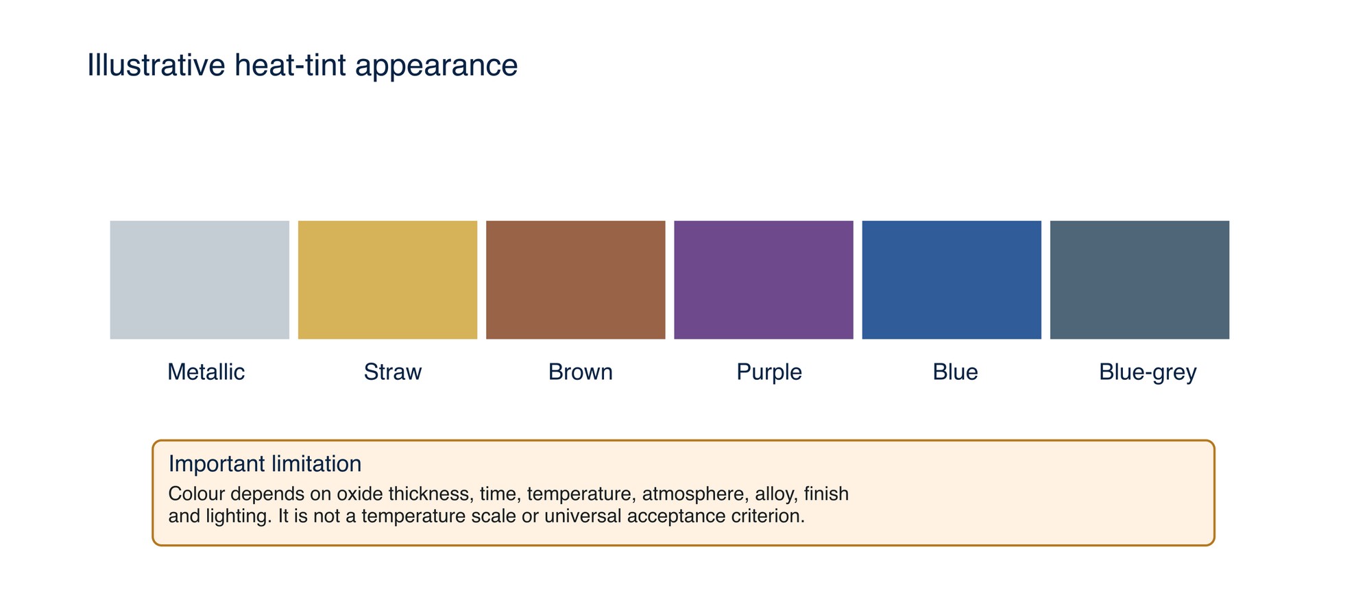
Heat tint forms when heating changes the oxide on the stainless surface. Colour depends on oxide thickness and optical interference, but it also depends on grade, atmosphere, surface condition and time-temperature history. Research and industry guidance link heat-tint oxides and the chromium-depleted region beneath them with reduced local corrosion resistance. [S001; S002; S011; S012]
What colour can and cannot tell you
Colour can locate a thermally affected area and help compare a process trial. It cannot, by itself:
- identify the stainless grade;
- state a universal peak temperature;
- prove the depth or chemistry of the affected region;
- prove corrosion resistance after removal; or
- define how much material must be removed.
Grinding response to heat tint
The visible oxide may cut differently from the base metal. Aggressive local removal can erase colour while creating a low spot, deeper scratch pattern or another hot zone. A finer brightening stage can hide rather than remove the preceding damage. The controlled route is to define the required oxide-removal and corrosion-restoration method, remove only within the geometry allowance, and verify the complete surface condition.
Worldstainless describes pickling as removing a thin metal layer and passivation as improving the passive layer; both are controlled chemical treatments, not interchangeable workshop cleaning labels. [S001; S016] This handbook intentionally gives no acid recipe, concentration, dwell time or neutralisation instruction. Current product data, SDS, Malaysian chemical controls and an approved procedure are mandatory. [S009; S017]
Embedded iron contamination
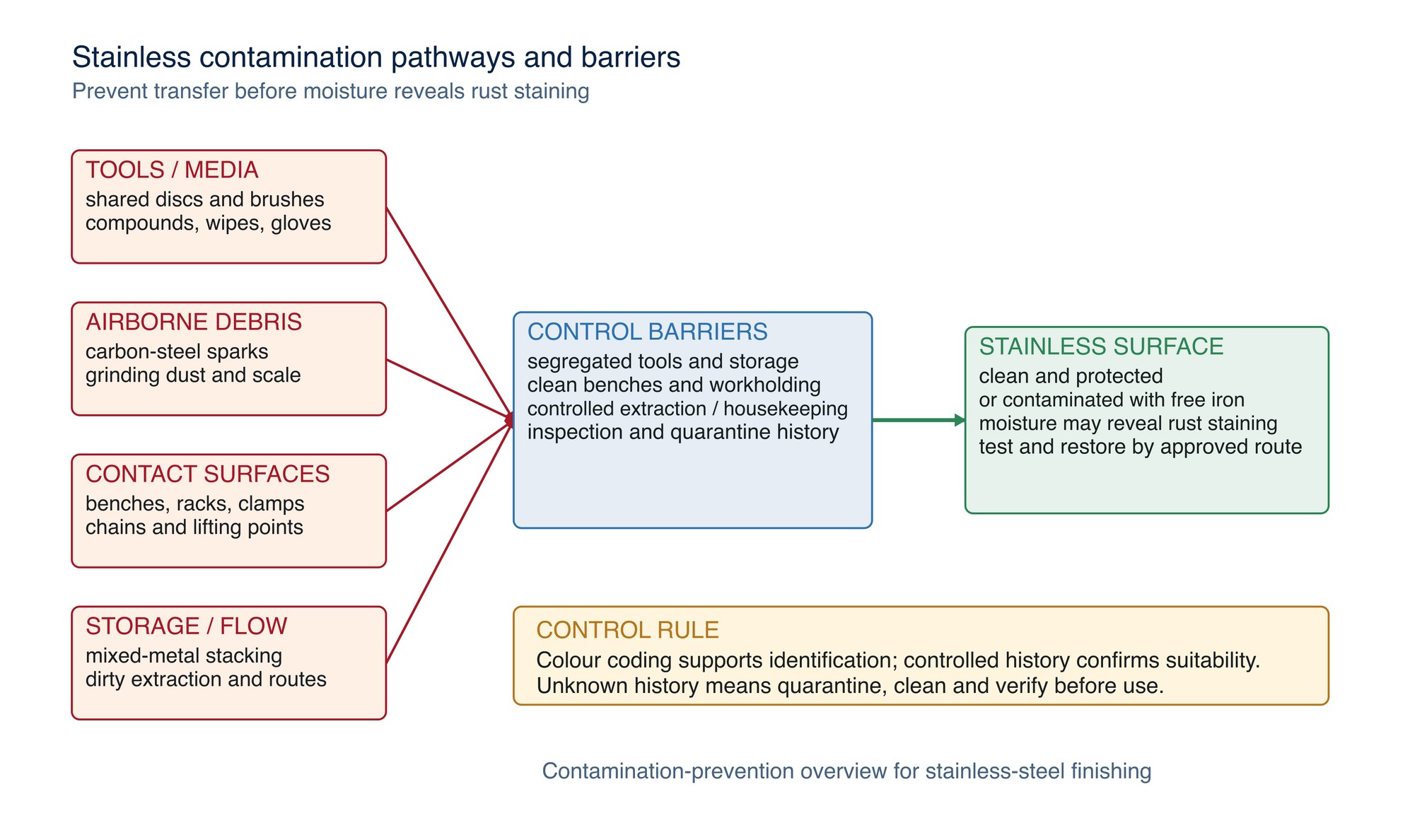
Iron contamination is foreign ferrous material on or embedded in stainless steel. BSSA identifies non-stainless processing equipment, mixed-metal tools, handling equipment, cutting debris and grinding dust as common pathways. When contamination becomes wet, rust staining can appear. [S027]
Typical contamination examples
- a flap disc previously used on carbon steel is moved to a stainless job;
- carbon-steel grinding sparks or dust settle on stored stainless sheet;
- a stainless component is placed on a dirty steel bench or rack;
- a carbon-steel wire brush is used to clean a stainless weld;
- shared clamps, chains or fork surfaces leave contact marks;
- contaminated polishing compound, wipes or extraction debris are carried into a final stage; or
- clean parts are stored beneath active carbon-steel fabrication.
These are preventable process failures. A stain is the visible effect; embedded or deposited iron is the cause. Removing only the brown colour without controlling the source allows recurrence.
Stainless-only means controlled history
A “stainless-only” label is credible only when the history is controlled. The system should include:
- dedicated or validated-clean tools, abrasives, brushes, compounds and wipes;
- physically separated, identified storage;
- clean benches, workholding, lifting equipment and protective surfaces;
- extraction and housekeeping that prevent carbon-steel dust migration;
- gloves and handling practices that do not transfer debris;
- inspection before use and quarantine of uncertain items; and
- records linking tools and consumables to the permitted material route.
Colour coding helps identification but does not remove contamination. If the history is uncertain, treat the item as contaminated until it is cleaned and accepted under the authorised method.
Finish control: grit is an input, not the result
BSSA notes that grinding, polishing, brushing, buffing and a final grit number do not fully define a stainless finish. Pressure, time, feed, wet or dry operation, starting condition and abrasive medium also affect the result; agreed samples may be required. [S028]
| Visible observation | Possible interpretation | Required confirmation |
|---|---|---|
| Cut rate falls while force rises | Loading, glazing, local work hardening or harder weld region | Inspect abrasive and workpiece; verify product suitability and condition |
| Blue, straw or dark band | Heat-tint oxide or other thermal effect | Compare with specified removal and corrosion-restoration requirement |
| Bright surface with lines remaining | Smearing or polishing over a deeper scratch | Clean and inspect under directional light; verify previous pattern removal |
| Brown specks after moisture exposure | Deposited or embedded ferrous contamination | Use the specified contamination test and trace the source |
| Wavy reflection or changed edge line | Distortion, thinning or geometry loss | Measure against drawing and process allowance |
| Uniform colour but inconsistent lay | Mixed contact direction, dwell or media condition | Compare with approved comparator and direction requirement |
Scratch direction and matching
Directional finishes require control of lay, overlap, contact support and lighting. A repair that matches from one viewing angle can stand out after installation. Record the approved sample, viewing direction, illumination and protected boundary. Feathering must not widen indefinitely into accepted parent surface.
Before-and-after examples
The following examples show how starting condition and finish direction change the application approach.
- Weld blend on a visible panel. Before: raised weld transition, surrounding mill finish protected, no tint outside the controlled zone. After: profile within drawing allowance, preceding scratches removed, lay aligned to the comparator, no new tint, distortion or contamination, and cleaning route completed.
- Carbon-steel dust exposure. Before: brown specks after wetting and mixed-metal work nearby. After: contamination source isolated, surface tested and restored under the approved procedure, complete rinse and inspection recorded, and storage controls corrected.
- Heat-tinted thin sheet. Before: concentrated blue band and local waviness. After: stop-work investigation completed; geometry and corrosion requirement determine repair or rejection. Colour removal alone is not acceptance.
- Brushed handrail scratch. Before: isolated scratch crossing the original lay. After: repair boundary, direction and gloss match the approved comparator without flattening the profile or spreading contamination.
Cleaning and surface-restoration flow
Cleaning removes soil; decontamination removes foreign material; pickling removes oxide and a thin metal layer; passivation supports the passive surface. These words must not be used interchangeably. [S001; S016; S027]
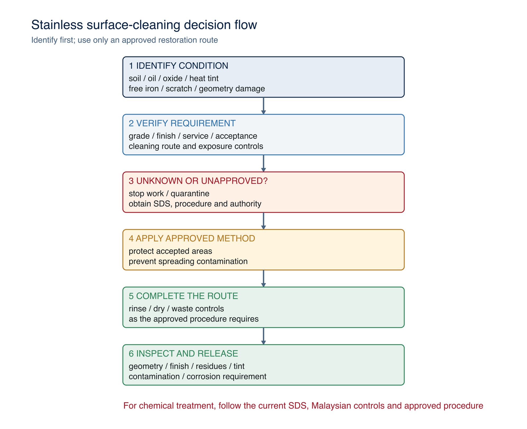
Controlled route
- Identify the soil, oxide, contamination or damage and its likely source.
- Confirm grade, finish, service duty and acceptance requirement.
- Stop if the contaminant or coating is unknown or if a chemical route lacks current SDS and approval.
- Protect accepted surfaces and segregate the work from ferrous debris.
- Apply the least damaging authorised method that can achieve the specified result.
- Rinse, dry and manage waste exactly as the approved procedure requires.
- Inspect geometry, finish, residues, tint and contamination using the specified method.
- Record acceptance or route the work to rework, engineering review or rejection.
Chemical cleaning can etch or change an appearance, and abrasive cleaning can spread embedded particles or change texture. BSSA advises ensuring contamination is removed rather than redistributed. [S027] The selected method must therefore be evaluated against both corrosion function and visible finish.
Process-control checklist
- [ ] Stainless grade, condition and service duty are verified.
- [ ] Required geometry, finish code, lay, comparator and inspection method are available.
- [ ] Weld, heat tint, scale, coating, oil and suspected contamination are identified.
- [ ] Machine, guard, mounting and abrasive rated-speed compatibility are confirmed.
- [ ] Product instructions cover the stainless grade and intended operation.
- [ ] Tools, media, workholding, bench, extraction and storage have controlled stainless-only history.
- [ ] Carbon-steel sparks and dust cannot reach the work or clean consumables.
- [ ] Thin sections, edges and distortion-sensitive zones have defined checks and stop limits.
- [ ] Cleaning, pickling or passivation work has an approved procedure, current SDS and waste controls.
- [ ] A representative trial records product, machine, settings, time, wear, heat, scratches and finish.
- [ ] Final inspection covers geometry, texture, direction, cleanliness, tint, contamination and corrosion requirement.
- [ ] Rework and escalation authority are known before production begins.
Practical stainless-steel application guidance
Choose abrasives declared suitable for the stainless grade and operation, and keep them segregated from carbon-steel use. Progress from geometry correction to scratch refinement with the fewest effective stages, inspecting heat tint, distortion, embedded contamination and finish direction separately.
Acceptance depends on the component's service: decorative work, food-contact equipment, pharmaceutical fabrications and corrosion-critical assemblies may require different cleaning, restoration and inspection routes. Chemical treatment must follow its current technical and safety information and the workplace chemical assessment. Refer to the product label, Technical Data Sheet, or MKTECH representative.
Source-code key
Every [Sxxx] citation in this chapter resolves in the Complete source index at the end of the handbook. Source codes identify the publication supporting the stated principle and do not create an MKTECH product specification.
How Abrasives Remove Material
The How Abrasives Remove Material chapter appears on the following page of the printed handbook (page 37), outside this chapter extract.