

Production engineers, supervisors, operators, QA/QC personnel, maintenance teams, safety personnel, procurement staff and technical sales personnel
The mechanics of abrasive material removal in hand-held and related industrial grinding and finishing. This chapter explains control logic but does not establish an MKTECH product recommendation, universal speed, pressure, angle, removal rate or service-life claim.
Use an abrasive only for its intended operation and only when its identity, condition, dimensions, maximum operating speed, mounting system, guard, machine compatibility and work-material suitability are verified. Never exceed the abrasive or machine rating. Stop for damage, unknown history, missing instructions, abnormal vibration or an unverified application. [S007; S018; S032]
Chapter objectives
After this chapter, the reader should be able to:
- describe how individual grains rub, plough and cut as engagement changes;
- explain chip formation, side flow and the origin of heat at the contact;
- distinguish grain fracture, bond fracture and useful edge renewal;
- diagnose glazing, loading and ordinary abrasive wear separately;
- relate contact force, contact area and surface speed to the cutting response;
- measure removal rate without ignoring finish, geometry, heat or abrasive consumption; and
- design a controlled trial that identifies a stable process window.
An abrasive is a field of small cutting edges
A grinding product is not a single blade. It presents many hard grains to the workpiece. Each active grain has its own protrusion, orientation, edge radius and local support. Only a portion of the visible abrasive surface is carrying useful load at any instant.
In a bonded grinding wheel, abrasive grains are held by a bond and separated by pores. The pores provide clearance for chips and can assist fluid or air movement in processes designed for them. [S029] Coated abrasives place grain on a backing with adhesive layers; flap discs arrange coated abrasive pieces around a hub; nonwoven products hold abrasive in a compliant fibre network. The removal mechanism is related, but the support, chip clearance, wear and failure modes are not identical.
This distinction matters when diagnosing a problem. A hard bonded wheel, a flexible fibre disc and a nonwoven finishing product cannot be corrected by the same generic instruction. Product construction, work material, operation and machine must be identified first.
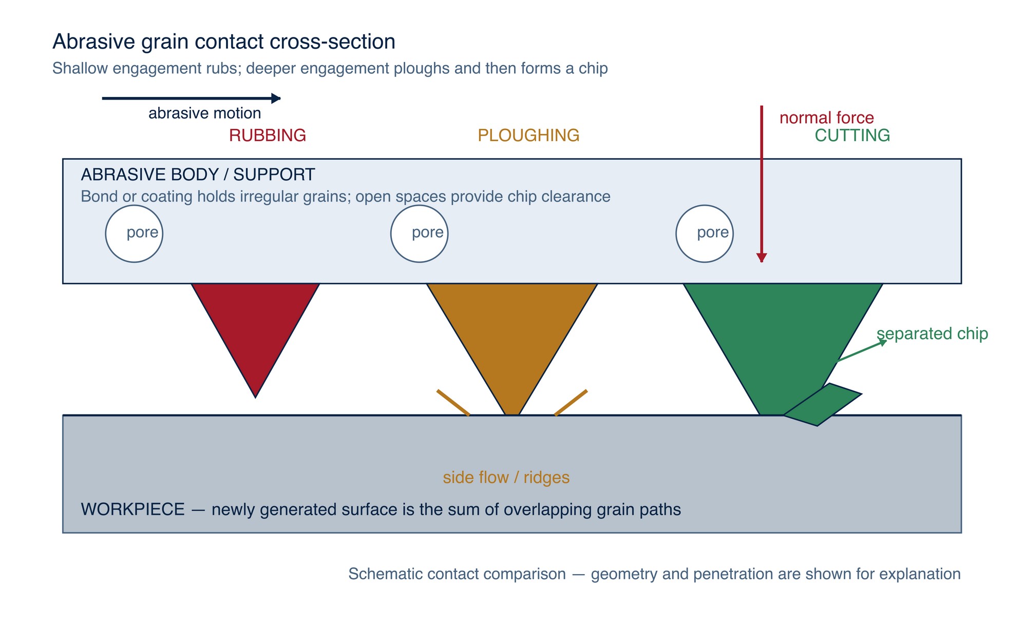
Rubbing, ploughing and cutting
Grinding research commonly separates grain–workpiece interaction into rubbing, ploughing and chip-forming cutting. The modes can exist together across one contact zone; they are not three independent machines or a simple switch at one universal depth. [S030; S031]
Rubbing
At very shallow engagement, a rounded or poorly oriented grain slides across the surface without forming a useful chip. Elastic and small plastic deformations occur, friction rises and energy is spent with little volume removed. Rubbing is therefore not “no effect”: it can heat, polish, smear or work the surface while the operator sees a weak cut.
Typical contributors include a dull or capped grain, insufficient engagement for the selected abrasive, excessive support compliance, a loaded face, poor approach geometry, dwelling on a broad contact patch or a product not suited to the material.
Ploughing
With greater engagement, the grain pushes material sideways and ahead. Ridges or pile-up form along the groove. Some material may later be removed by following grains, but the first interaction has displaced more material than it has separated as a chip.
Ploughing consumes force and produces plastic deformation. On ductile material it may create side flow or smearing. On thin, edge-sensitive or finished components, the displaced material and concentrated force can change surface form even before a visible chip stream appears.
Cutting
When engagement and grain geometry permit, material shears and separates as a chip. Cutting converts a larger share of the interaction into useful removal, but it still generates heat and force. The chip must leave the contact without repeatedly welding, clogging clearance spaces or damaging the newly generated surface.
The practical objective is not to eliminate all rubbing and ploughing; a real abrasive contact contains many grain orientations. The objective is to maintain a stable population of effective cutting edges so removal, force, wear and surface condition remain within the approved process window.
How a chip forms
Chip formation starts when an active grain penetrates far enough to overcome the work material’s resistance to deformation and separation. The local engagement depends on more than a nominal grit size. It is influenced by:
- grain protrusion, shape, sharpness and orientation;
- the number of grains sharing the load;
- contact force and actual contact area;
- abrasive stiffness, backing or bond support;
- surface speed and work motion;
- material hardness, ductility, microstructure and temperature;
- previous scratches, scale, weld condition and local geometry; and
- the ability of the product to clear chips and expose active edges.
The grain first meets a surface that is not perfectly flat. It may touch a high point, slide, indent, create side flow and then form a chip. A following grain encounters the groove and ridges left behind. The final surface is the combined result of many overlapping interactions, not a copy of one ideal groove.
This explains why nominal grit alone cannot predict cut rate or finish. Two products with the same marked grit can differ in grain type, shape, orientation, coating, bond, spacing, backing, flexibility and active-grain density. The workpiece and machine add further variation.
A useful observation rule
When removal falls, do not automatically add force. First inspect whether the abrasive is still presenting open, sharp cutting edges. More force applied to a glazed or loaded surface can increase heat, smearing, wear or damage without restoring efficient chip formation.
Grain fracture, bond fracture and self-sharpening
An abrasive edge changes during use. It can wear flat, fracture, become covered by adhered work material, pull out of its support or break away with part of the bond or backing. These changes determine whether the cutting surface renews or deteriorates.
Grain fracture
Grain fracture breaks an abrasive particle and can expose a new sharp edge. Controlled microfracture can be useful when the new edge remains supported. Large or premature fracture can waste abrasive, disturb the finish or create unstable cutting.
Bond fracture or grain release
In a bonded wheel, fracture of the bond or loss of retention can release a dull grain and expose another. The required balance depends on the wheel specification and application. A bond that retains dull grains too long can contribute to glazing; a system that releases grains too readily wears rapidly and may lose form. [S025; S029]
For coated and nonwoven products, edge renewal occurs through different combinations of grain fracture, coating wear, grain loss, flap exposure or fibre breakdown. Use the manufacturer’s construction-specific explanation rather than calling every wear event “bond fracture.”
Self-sharpening
Self-sharpening is the controlled renewal of useful cutting edges through grain fracture, grain release or exposure of fresh abrasive. Manufacturer claims about self-sharpening apply to identified products and conditions; they are not proof that an abrasive will remain sharp in every material or at every load. [S004; S005]
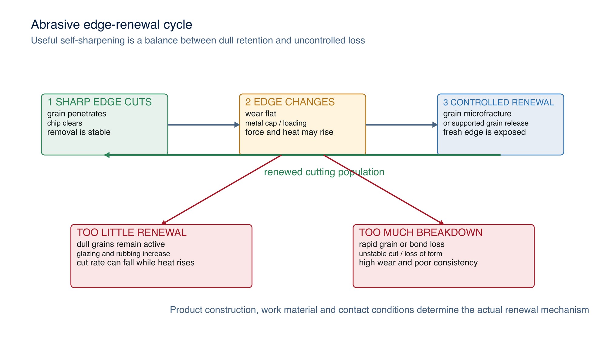
Glazing, loading and wear are different diagnoses
Glazing and loading can both produce a falling cut rate and rising force, but the corrective logic differs.
| Condition | Surface evidence | Confirmation and control |
|---|---|---|
| Glazing | Smooth, shiny or flattened abrasive points; cut rate falls | Inspect under suitable light or magnification; compare force and removal trend |
| Loading | Work material or debris packed between or over grains | Identify the deposit and confirm chip clearance and product/material suitability |
| Normal wear | Predictable edge and backing or bond consumption | Compare with the validated wear pattern and replacement criterion |
| Excessive breakdown | Rapid grain loss, edge collapse or loss of form | Stop; inspect mounting, contact, product and work condition |
| Smearing or capping | Metallic streaks or adhered caps on active areas | Use only an authorised cleaning method; reassess sharpness and chip clearance |
Do not “dress,” clean, strike, scrape or otherwise modify an abrasive unless that action is specifically permitted for the product and equipment. A method appropriate for a stationary bonded wheel may be unsafe for a hand-held coated or bonded product.
Diagnostic sequence
- Stop: isolate the machine safely.
- Identify: verify the product and confirm that inspection or cleaning is permitted.
- Examine: inspect the active surface, edge, backing or bond and the workpiece scratch pattern.
- Compare: assess removal, force, heat, sound and vibration against the established baseline.
- Diagnose: determine whether the dominant issue is glazing, loading, wear, damage, work-material change or machine condition.
- Correct: act only through the product instructions and approved process; replace uncertain or damaged abrasive products.
Force, contact area and surface speed
Contact force is not the same as pressure at each grain
Operator force is distributed through the product, contact patch and active grains. The same applied force on a narrow edge contact and a broad supported contact produces different local loading. Contact angle, product flexibility, backing, wheel geometry, work shape and surface irregularity all change the real patch.
Increasing force can increase grain penetration and removal while the abrasive continues to cut stably. Beyond the useful range it can overload grains, collapse a flexible backing, widen the contact, increase ploughing and rubbing, accelerate wear, overheat the work or damage the product. [S005; S025; S030]
The controlled variable is therefore not “push harder.” Record the machine, product, contact geometry and an objective force method where the application permits. For hand-held work without force instrumentation, use a validated technique, stable posture and observable process limits rather than a guessed kilogram value.
Surface speed changes the interaction
Surface speed is the linear speed at the abrasive contact. It depends on rotational speed and product diameter. As a product wears and its diameter changes, surface speed can change even if machine rpm remains constant.
Speed influences the number of grain contacts per unit time, load sharing, chip thickness, force, heat, wear and finish. The relationships are not universally linear: a higher permitted speed can distribute load across more contacts, but it can also alter heat generation, backing behaviour or product wear. [S025; S029]
Maximum operating speed is a safety ceiling, not a recommended production target. The selected machine setting must satisfy both the abrasive and machine instructions and remain within the validated application window. [S032]
Motion and dwell
Travel speed, overlap and dwell determine how repeatedly the abrasive visits one location. A process can have the correct machine speed and still overheat or gouge because contact motion is unstable. Record how the tool is moved, not only the dial setting.
Where the energy goes
The machine supplies mechanical power. At the contact, energy is spent in chip-forming shear, plastic displacement, friction, abrasive fracture, bond or backing deformation, vibration and other losses. A significant portion becomes heat in the workpiece, chip, abrasive and surrounding air or fluid. [S031]
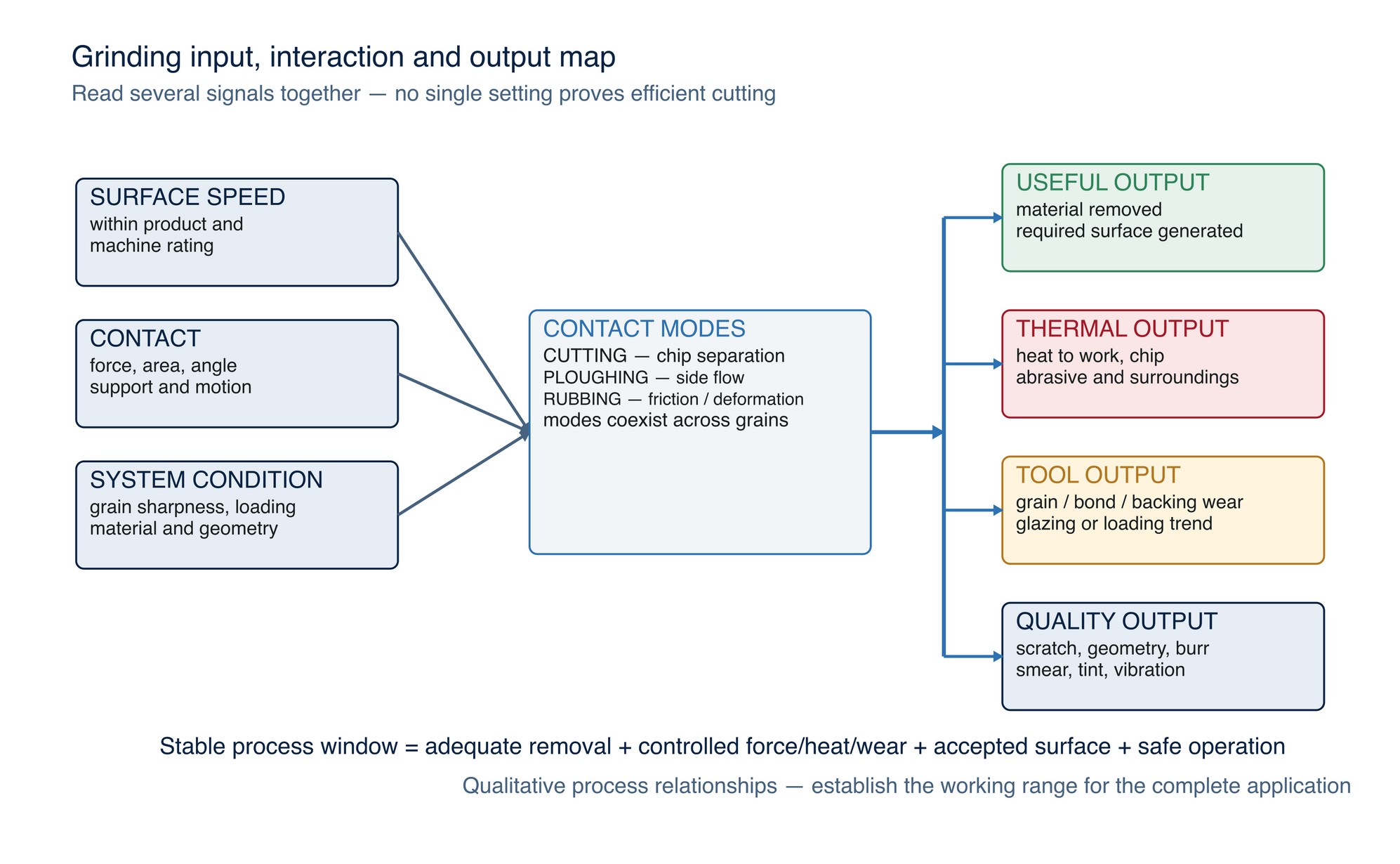
Heat formation is therefore a process signal, not a single-variable diagnosis. A rising workpiece temperature may accompany dull grains, loading, excessive dwell, a broad or edge-concentrated contact, unsuitable force, poor chip clearance, high removal demand or a material change. The same visible temperature can conceal different causes.
Monitor a useful set of signals together:
- removal per unit time;
- force or a repeatable force proxy;
- workpiece temperature or approved thermal indicator;
- abrasive mass, diameter or other wear measure;
- spark, chip or debris behaviour where safe and relevant;
- scratch pattern, burr, smear, tint and geometry; and
- sound and vibration trend.
Material-removal rate without false productivity
Material-removal rate is removed volume divided by grinding time. In a controlled coupon trial, volume can be measured directly or estimated from mass loss divided by verified material density. The measurement method, scale resolution, cleaning method and timing boundary must be recorded.
A high removal rate is not automatically a good process. A trial fails if it achieves fast removal by overheating the work, changing geometry, consuming excessive abrasive, contaminating the surface, creating an unacceptable scratch pattern or exceeding safety and product limits.
Use a balanced trial record:
- starting and final mass or dimensions;
- active grinding time and total cycle time;
- product identity, batch where required and initial/final condition;
- machine identity, rpm setting and measured speed where required;
- contact geometry, tool motion and force-control method;
- material identity, hardness/condition, geometry and starting surface;
- removal rate and abrasive-consumption measure;
- temperature or thermal observation method;
- final surface, dimensional and defect results; and
- stop events, replacements and operator observations.
Controlled comparison rule
Change one planned factor at a time where practical, or use an authorised structured experiment when interactions must be studied. Repeat enough trials to separate a stable trend from operator and material variation. Do not publish a percentage improvement from one unreplicated coupon.
Establishing a stable process window
A useful process window is the region in which the abrasive cuts predictably, removal is adequate, force and heat remain controlled, wear is acceptable, and the resulting geometry and surface meet the requirement. It sits inside the safety and product limits; it does not redefine them.
- Verify the material, starting condition, required removal and acceptance criteria.
- Verify machine, guard, mounting, abrasive identity, rated speed and intended operation.
- Choose a conservative manufacturer-supported starting condition.
- Run a representative coupon or sacrificial-zone trial with recorded motion and contact.
- Measure removal, time, abrasive wear, heat, geometry and surface condition.
- Inspect the abrasive for glazing, loading, damage and edge-renewal behaviour.
- Adjust only one authorised variable or follow the approved experiment plan.
- Repeat and confirm the result across realistic variation.
- Define replacement, stop-work and escalation criteria.
- Release the method only after technical, safety, quality and MKTECH approval.
Process-control checklist
- [ ] Material identity, condition, geometry and required result are verified.
- [ ] Abrasive construction, product code, dimensions and intended operation are known.
- [ ] Machine, guard, flange/backing system and rated-speed compatibility are confirmed.
- [ ] The active surface is undamaged and free from unverified modification.
- [ ] Contact geometry and tool motion are defined for the actual product.
- [ ] Removal, force, heat, wear, vibration and surface signals have a baseline.
- [ ] Glazing, loading and normal wear have separate inspection criteria.
- [ ] Product replacement and stop-work limits are established before production.
- [ ] The trial measures removal rate together with geometry and surface acceptance.
- [ ] Dust, spark, fire, noise and exposure controls match the material and process.
- [ ] Results are recorded by product, machine, material and operator technique.
- [ ] Every product or performance statement is supported by the cited technical source or measured application result.
Applying removal principles in practice
Select a product whose declared construction and application suit the work material, machine, contact geometry and required output. Maintain a cutting action by using stable contact, controlled travel and only the working face permitted by the product instructions. If removal slows, inspect for loading, glazing, wear, machine-speed loss and poor support before changing force.
Compare products by accepted output rather than removal rate alone. Include finish, heat, geometry, rework, operator exposure and consumable use in the comparison. Refer to the product label, Technical Data Sheet, or MKTECH representative.
Abrasive Grain Types
The Abrasive Grain Types section appears on the following page of the printed handbook (page 45), outside this chapter extract.