

Production managers, workshop supervisors, safety and health personnel, operators, maintenance teams, technical buyers, trainers and application personnel involved in grinding, cutting, sanding or polishing
Fundamental controls for abrasive products and powered tools, including risk assessment, competence, product marking, compatibility, receiving and storage, pre-use inspection, mounting, guarding, workpiece support, safe start-up, operating behaviour, spark control, stop-work conditions, post-use isolation and troubleshooting.
Safety is achieved by controlling these hazards before start-up and maintaining that control until the tool has stopped and the work has cooled. The fundamental rule remains: control the hazard at source and use the appropriate specialist controls before starting. Troubleshooting must preserve the safety boundary. Never diagnose a suspected mounting, guard, spindle or product fault while the tool is energised or coasting. [S275; S280; S283; S284]
Safe abrasive work depends on the complete system: a suitable abrasive, a compatible tool, correct mounting and guarding, a stable workpiece, a controlled environment and a trained operator using the product only for its marked purpose.
Abrasive products remove material by operating at high speed and concentrating force at a small contact area. The useful cutting action is therefore accompanied by stored rotational energy, fragments, sparks, hot metal, dust, noise, vibration and reaction forces. Safety is achieved by controlling these hazards before start-up and maintaining that control until the tool has stopped and the work has cooled. [S275; S280; S283; S284]
Chapter objectives
After this chapter, the reader should be able to:
- identify the principal hazards of grinding, cutting, sanding and polishing;
- apply the hierarchy of control to the task, work area, tool and abrasive product;
- define the competence required for selection, mounting, operation and supervision;
- interpret the product label and recognise when exact technical information is required;
- verify tool–accessory compatibility before mounting;
- receive, handle and store abrasive products without avoidable damage;
- inspect tools, guards, mounting parts and abrasive products before use;
- mount common abrasive products without improvisation;
- secure the workpiece and control the fragment, spark and reaction-force zones;
- use controlled start-up and operating techniques for grinding and cutting;
- recognise stop-work conditions and respond safely; and
- troubleshoot unsafe symptoms without attempting to work through them.
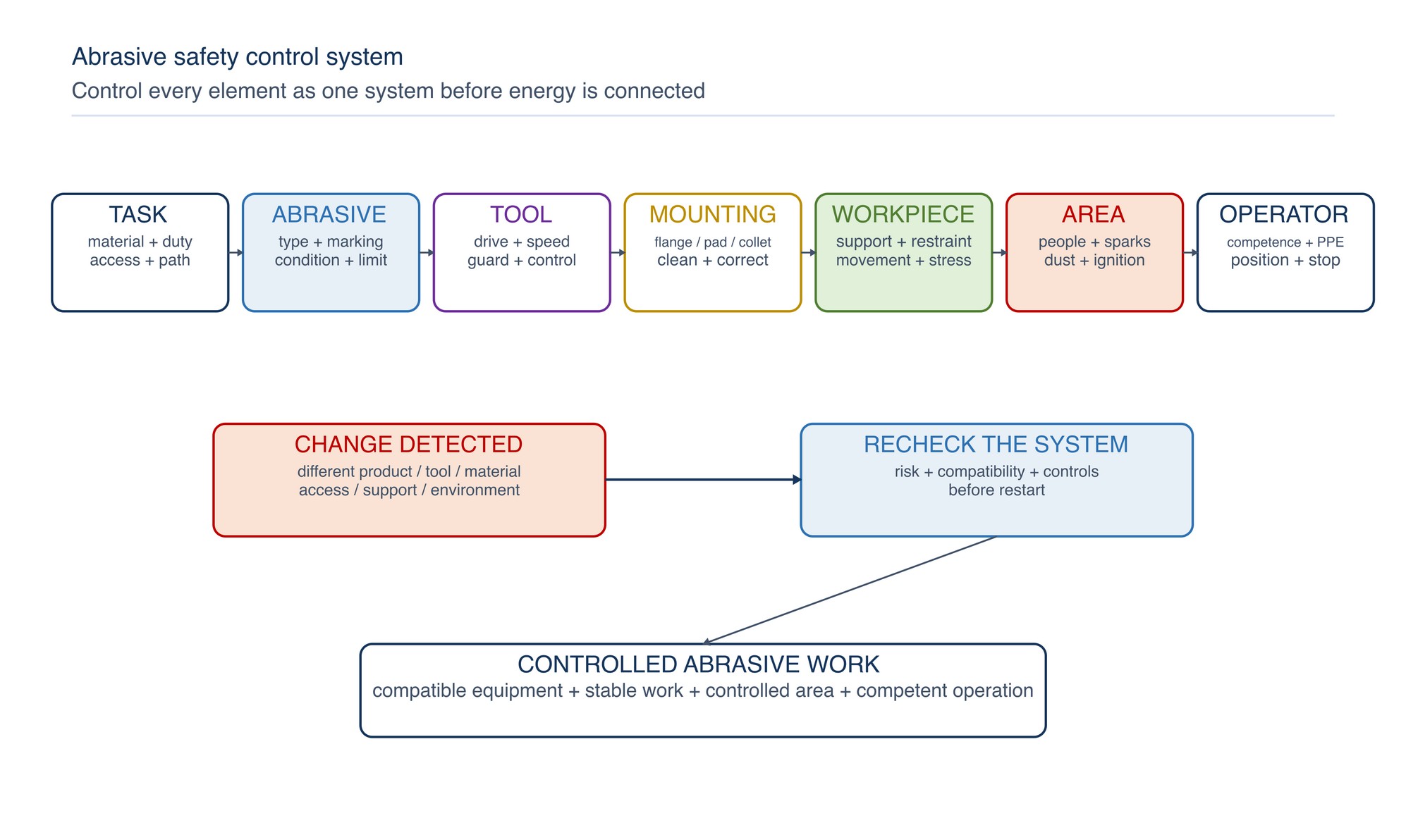
Treat abrasive work as a complete safety system
Do not assess an abrasive product in isolation. A suitable product can become unsafe when fitted to the wrong tool, mounted with incorrect parts, used without the specified guard, applied to an unstable workpiece or operated in an uncontrolled area.
Review seven connected elements before work begins:
- Task: material, operation, access, required finish and cut or grinding path.
- Abrasive: product family, dimensions, intended use, marking, condition and attachment.
- Tool: power source, spindle or drive, speed, capacity, guard, handle, controls and maintenance condition.
- Mounting system: flange, backing pad, nut, adaptor, collet or other manufacturer-specified parts.
- Workpiece: mass, support, restraint, residual stress, movement and behaviour as material is removed.
- Environment: people, combustible material, cylinders, cables, ventilation, wet conditions, confined areas and hazardous atmospheres.
- Operator: training, authorisation, physical control, body position, PPE and readiness to stop.
If one element changes, review the system again. A different wheel diameter, material grade, power tool, access position or support arrangement can change the hazard and the correct control.
Apply the hierarchy of control
Personal protective equipment is important, but it is the final layer rather than the starting point. Use the hierarchy of control to reduce exposure at source. Malaysian workplace duties place emphasis on safe plant, safe systems of work, information, instruction, training, supervision and risk assessment. [S275]
| Control level | Abrasive-work application | Practical example |
|---|---|---|
| Eliminate | Remove the abrasive task or hazardous access | Order a profile nearer to final size; redesign access so finishing is unnecessary |
| Substitute | Use a less hazardous process, product or material | Use a lower-dust method or a product intended for the required operation |
| Engineering | Separate people from energy, fragments, dust and sparks | Machine guard, enclosure, local extraction, screen, fixture or remote handling |
| Administrative | Control competence, sequence, area and duration | Authorisation, safe-work procedure, hot-work permit, inspection and exclusion zone |
| PPE | Protect against remaining exposure | Suitable eye, face, hearing, respiratory, hand, body and foot protection selected through risk assessment |
Choose controls for the actual process. A screen may protect nearby personnel from sparks but will not control airborne dust unless airflow and capture are designed for that purpose. A face shield supplements the selected eye protection; it is not a substitute for guarding or a reason to stand in the likely fragment path.
Recognise the principal hazards
| Hazard | How it develops | Primary controls |
|---|---|---|
| Abrasive breakage or accessory release | Damage, incompatible speed or mounting, side loading, impact, excessive force or incorrect support | Correct selection, inspection, mounting, guard, controlled start-up and stable technique |
| Contact with moving product | Exposed abrasive, loss of balance, uncontrolled run-down or reaching across the tool | Guard, two-handed control where designed, body position, isolation and complete stop |
| Kickback or reaction force | Binding, pinching, edge impact, twisting in a cut or sudden contact | Secure workpiece, planned path, correct product, stable grip and avoidance of jamming |
| Sparks, hot particles and hot workpiece | Material removal and friction | Direct discharge, clear combustibles, hot-work controls, fire watch where required and cooling time |
| Dust, fume and mist | Workpiece, coating, abrasive and process fluid are fragmented or heated | Material identification, source capture, ventilation, process selection and suitable respiratory protection where required |
| Noise and vibration | Tool, abrasive, workpiece resonance and contact conditions | Suitable equipment, maintenance, exposure control, technique and health-protection programme |
| Entanglement | Loose clothing, hair, jewellery, gloves or cables enter rotating parts | Clothing and work-area control; keep hands and loose items clear |
| Electrical, pneumatic or hydraulic energy | Damaged supply, wet conditions, hose failure, unintended start or stored pressure | Inspection, suitable supply, isolation, controlled connection and maintenance |
| Workpiece movement or collapse | Poor restraint, cut closure, released stress or unsupported offcut | Fixture and support both sides of the operation; plan the final separation |
Chapters 047 to 050 develop PPE, dust, noise, vibration, spark, fire and explosion control in greater depth. The fundamental rule remains: control the hazard at source and use the appropriate specialist controls before starting.
Define competence and authorisation
Selection, mounting and operation require practical competence, not familiarity alone. Training should cover the product families used at the site, label interpretation, correct mounting systems, tool inspection, guarding, operating technique, abnormal conditions and emergency response. FEPA identifies training as a foundation of professional abrasive safety practice. [S285; S286]
Supervisors should authorise personnel according to the tasks they can perform. Useful categories include:
- select a product for a defined application;
- inspect and issue abrasive products;
- mount products on portable tools;
- mount wheels on stationary machines;
- operate specific tool or machine types;
- adjust work rests, guards or extraction systems;
- isolate and maintain equipment; and
- train or assess other personnel.
Competence should be refreshed when equipment, product families, materials, work methods or site conditions change, and after an incident or unsafe observation. New personnel should work under direct supervision until they demonstrate correct selection, mounting, start-up, control and stop-work decisions.
Read the abrasive product before selecting it
The label and product marking are part of the safety system. Bonded-abrasive marking is addressed internationally by ISO 525, while product standards define shapes, dimensions and intended-use context for common wheel types. [S277; S278; S279]
Verify, as applicable:
- manufacturer and product identification;
- abrasive product family and shape or type;
- dimensions and bore or attachment;
- material or application marking;
- intended operation, including grinding, cutting, sanding or polishing;
- maximum permitted speed or other operating limit;
- direction of rotation where marked;
- required guard, flange, backing pad or support;
- restriction symbols and required PPE symbols;
- traceability or date information; and
- damage-free, legible condition.
Do not use colour alone to identify a product. Similar-looking products may have different construction, intended use or limits. Do not copy a speed, mounting arrangement or application from another diameter or product family.
When an exact product value is required: Refer to the product label, Technical Data Sheet, or MKTECH representative.
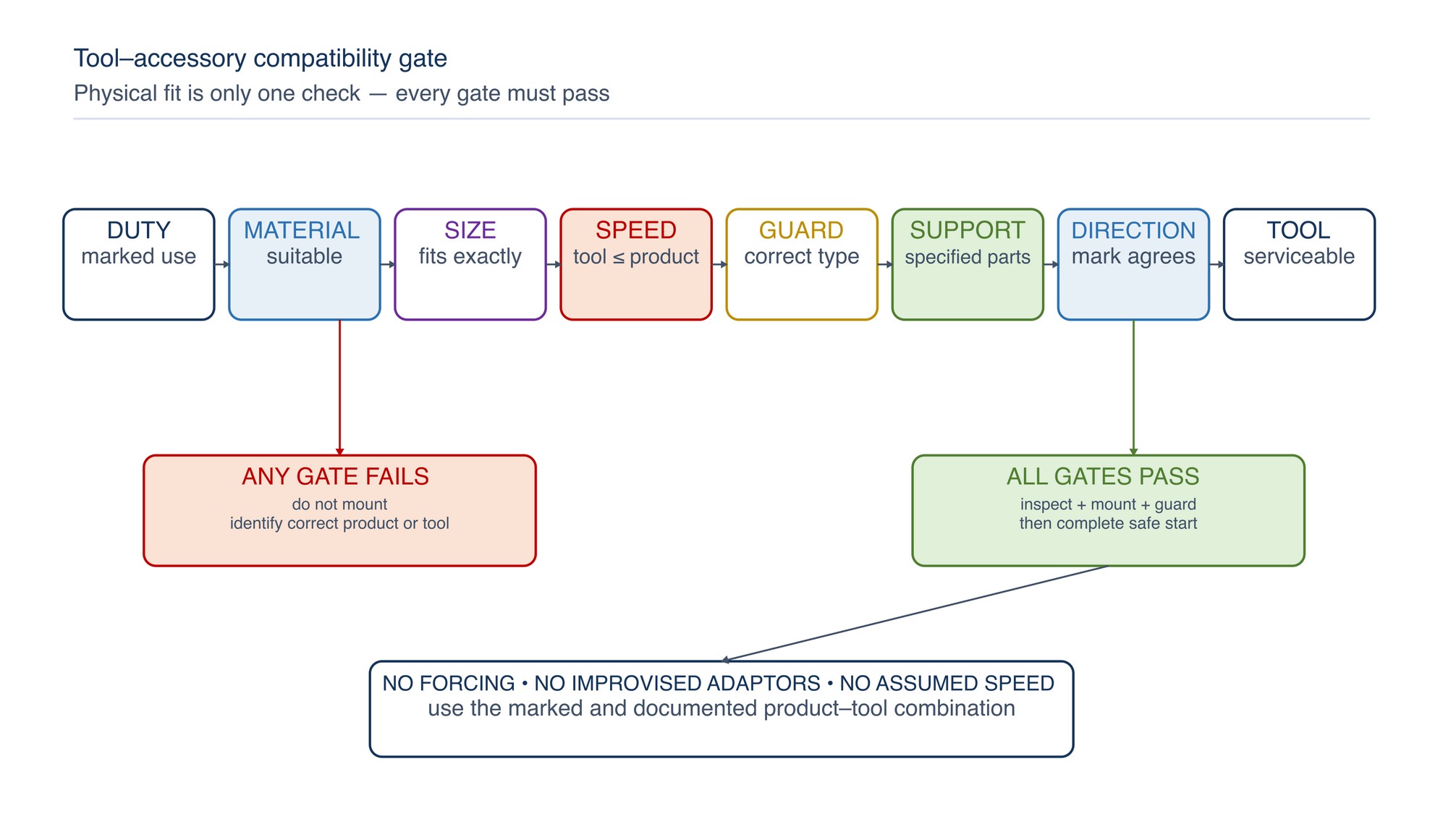
Pass every tool–accessory compatibility gate
Compatibility must be confirmed before the product is fitted. Electric grinders, pneumatic grinders, sanders, polishers and die grinders have different safety scopes and mounting systems; an attachment that physically fits is not automatically suitable. [S280; S281; S282; S283]
| Gate | Confirm | Reject when |
|---|---|---|
| Operation | Product is marked or documented for the intended grinding, cutting, sanding or polishing duty | Intended use is unknown or conflicts with the task |
| Material | Product is suitable for the workpiece and any coating or contamination | Material compatibility is uncertain or could create a reactive or contaminated process |
| Dimensions | Diameter, thickness, bore, thread, shank or belt size matches the tool and mounting system | Product requires forcing, alteration or an improvised adaptor |
| Speed | Tool maximum no-load speed does not exceed the product's marked maximum permitted speed | Either value is unreadable, unavailable or incompatible |
| Guard | Correct guard type and capacity can be fitted and positioned | Guard must be removed, opened beyond its design or substituted |
| Support | Specified flange, backing pad, blotter, nut, collet or other support is available and undamaged | Mounting parts are mixed, worn, distorted or improvised |
| Direction | Rotation and directional marking agree where direction is specified | Direction cannot be verified |
| Tool condition | Spindle, controls, handle, bearings, supply and safety devices are serviceable | Abnormal play, damage, unreliable control or overdue maintenance is present |
Do not alter a bore, reduce a product diameter by striking it, stack products, add packing or use makeshift washers to make an incompatible product fit. Use only the tool and mounting parts intended for the accessory system.
Receive and store abrasive products carefully
Abrasive products can be damaged without obvious packaging damage. Handle cartons and individual products without dropping, throwing, bending or allowing impact against hard edges. Check deliveries for correct identity, quantity, visible damage, moisture, deformation and legible labels before acceptance into controlled storage.
Store products:
- in the original packaging where practical;
- in a dry, stable environment away from water, excessive heat and direct sunlight;
- on suitable shelves or racks that support the product without distortion;
- away from traffic, vibration and falling-object exposure;
- so heavy items cannot crush lighter products;
- with product identity and stock rotation visible; and
- separately when quarantined, damaged or returned.
Store thin cutting wheels upright in a suitable compartment or supported as recommended by the manufacturer. Keep coated-abrasive belts and discs free from folds, kinks, edge damage and contamination. Do not hang heavy products from points that distort them. Allow products moved from a markedly different environment to stabilise in accordance with supplier guidance before use.
Inspect the complete setup before mounting
Isolate the tool from its energy source and verify that it cannot start. Clean the area and inspect under adequate light.
| Item | Check | Unsafe finding |
|---|---|---|
| Abrasive product | Identity, marking, cracks, chips, distortion, contamination, moisture damage and attachment condition | Damage, unreadable critical marking or uncertain history |
| Tool body | Housing, vents, fasteners, labels and general condition | Cracks, missing parts, severe contamination or unauthorised modification |
| Spindle or drive | Threads, shoulder, runout indicators, locking mechanism and cleanliness | Damage, excessive play, burrs or unreliable lock |
| Guard | Correct type, secure adjustment, adequate coverage and freedom from distortion | Missing, loose, cracked, modified or incompatible guard |
| Handle and controls | Side handle, trigger, lock-off, switch return and grip surfaces | Missing handle, sticking control or unintended-start risk |
| Mounting parts | Correct identity, matching set, flat contact, clean surfaces and sound condition | Mixed flanges, warped backing pad, damaged nut or improvised washer |
| Energy supply | Cable, plug, battery, hose, coupling, regulator and pressure condition | Cuts, exposed conductors, damaged pack, leaking hose or insecure coupling |
A ring test applies only to appropriate wheel types and must be performed using the correct method by trained personnel. It is not suitable for every wheel construction, size or mounting condition and does not replace visual inspection or product instructions.
Mount without force or improvisation
Use the specified mounting sequence for the tool and product. Keep spindle, flange and support surfaces clean. The product should seat without hammering, forcing or uncontrolled clearance. Use the correct tightening tool and method; excessive tightening can damage the product or mounting system, while insufficient tightening can allow movement.
General mounting sequence:
- isolate and verify zero energy;
- confirm the compatibility gates again at the point of use;
- inspect and clean all contact surfaces;
- install the specified inner support, flange, backing pad or collet;
- orient the abrasive product correctly;
- install the specified outer flange, nut or retaining part;
- tighten using the prescribed method without shock loading;
- rotate by hand where the design permits and check for interference;
- refit and position the guard and handle; and
- remove mounting tools and loose items before reconnecting energy.
Blotters, flanges, backing pads, nuts, collets and adaptors are functional safety components. Do not substitute them by appearance. Stationary-wheel mounting and dressing require the machine-specific procedure and trained personnel. [S284; S286; S287]
Position and verify the guard
Use the correct guard for the tool, accessory and operation. Position it between the operator and the most likely fragment or spark path while preserving safe access to the work. Secure the adjustment before start-up.
Never remove a guard because the product is difficult to access. Change the tool, product, fixture or work sequence so the operation can be completed with the designed protection in place. Do not use a grinding guard as an assumed substitute for a cutting guard, or enlarge, trim or bend a guard to create clearance.
On stationary machines, verify the enclosure, tongue or opening controls, work support, spark control and extraction arrangement according to the machine design and current site procedure. Adjustments near the wheel require isolation. ISO 16089:2025 provides a current safety framework for specified stationary grinding machines. [S284]
Secure and support the workpiece
The workpiece must remain stable through contact, material removal and final separation. Use a suitable vice, clamp, fixture or machine support. Do not hold a small component in one hand while operating a grinder in the other.
For cutting operations:
- support the main workpiece and offcut so neither traps the wheel;
- anticipate residual stress, spring movement and gravity;
- plan where the offcut will fall;
- keep supports clear of the wheel path;
- maintain a straight cut path; and
- protect hoses and cables from the cut, sparks and falling material.
For grinding operations, place the work so the tool can be controlled with balanced footing and without excessive reach. Avoid positions where a loss of contact will carry the tool into the body, another person, a cable or an unprotected edge.
Control the work area and spark path
Establish a clear operating zone before start-up. Keep other people outside the likely fragment, spark and reaction-force areas. Use suitable screens without creating reflected hazards, blocked exits or poor ventilation.
Inspect the spark path to its full travel, including downward gaps and areas behind the work. Remove or protect combustible materials, flammable liquids, gas cylinders, hoses, cables, glass, painted surfaces, vehicles and sensitive equipment. Apply the site's hot-work controls where sparks or heat can create ignition. Confirm that extraction equipment is suitable for the material and fire or explosion hazard.
Grinding or cutting a coated, plated, contaminated or unknown material can create hazardous airborne products. Identify the substrate and surface system before work. Do not grind containers, pipework or equipment that may retain flammable, toxic or pressurised contents until the authorised preparation and verification process has made the work safe.
Prepare the operator
Before connecting energy, confirm:
- training and authorisation for the tool and task;
- suitable eye and face protection for the hazard;
- hearing, respiratory, hand, body and foot protection selected by risk assessment;
- close-fitting clothing, secured hair and removal of jewellery;
- clean, dry grip surfaces and stable footwear;
- a correctly fitted side handle where the tool is designed to use one;
- balanced footing and sufficient room for the expected reaction force;
- safe routing of cable or hose; and
- clear communication with nearby personnel.
Glove selection requires care. Gloves may protect against sharp edges, sparks and hot surfaces, but loose or unsuitable gloves can introduce entanglement or reduce control. Select and use them according to the task, rotating-equipment risk and site assessment.
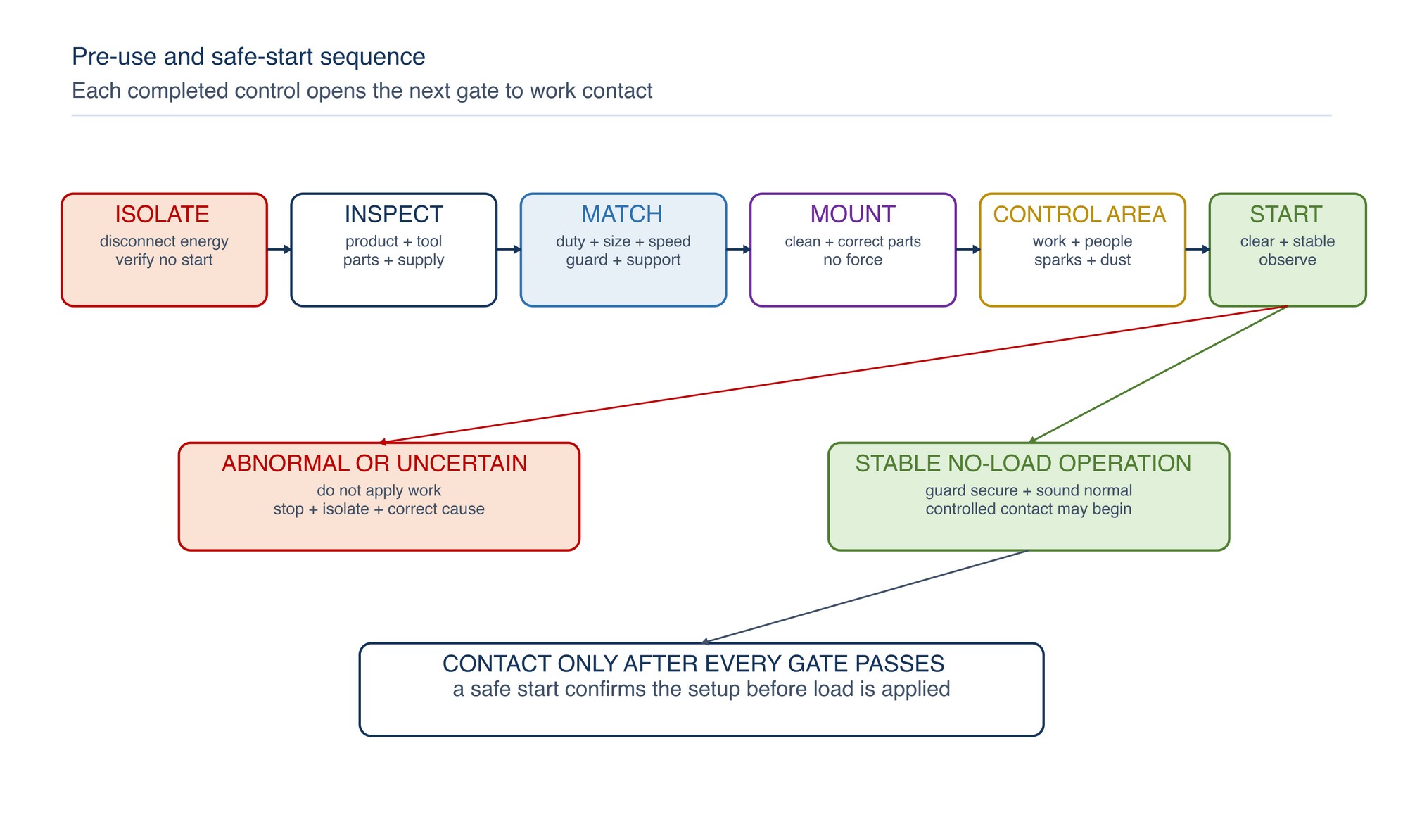
Use a controlled start-up sequence
Reconnect energy only after mounting, guarding, workpiece and area checks are complete. Hold a portable tool firmly in the intended operating posture with the accessory clear of the work. Keep yourself and others out of the likely fragment plane or discharge path.
Start the tool and allow it to reach stable no-load operation. Observe sound, vibration, runout, guard security and control response. Stop and isolate immediately if anything is abnormal. Conduct the manufacturer-specified test run for the actual product and tool before applying work.
Grind with controlled contact
Bring the abrasive to the work smoothly after stable running is confirmed. Use a grip, body position and movement that keep the tool under control if the contact force changes. Let the abrasive cut; excessive force increases heat, loading, wear, reaction force and the likelihood of damage without guaranteeing faster work.
Maintain the contact angle and direction appropriate to the product. Avoid striking the edge, bouncing, levering, deep uncontrolled gouging or allowing the tool body and guard to collide with the work. Keep moving where the process requires it so heat and wear are not concentrated in one point.
If cutting performance declines, stop and determine why. A worn, loaded, glazed, damaged or unsuitable product should be addressed through selection and controlled replacement, not greater force.
Cut without side loading or binding
Use a cutting-off wheel only for the operation permitted by its marking. Keep it aligned with the cut and apply force in the radial cutting direction. Do not use the side of a cutting wheel for grinding unless the product is specifically marked and documented for that combined duty. ISO 603-16 identifies flat and depressed-centre cutting-off-wheel types intended for hand-held cutting applications; product marking remains decisive. [S279]
Avoid twisting the tool in the kerf, forcing a change of direction, striking the wheel against the work or allowing the cut to close onto the wheel. If the tool stops or the wheel binds:
- release the control while maintaining a firm grip;
- hold the tool still until the wheel has completely stopped;
- remove energy and stabilise the workpiece;
- determine and correct the cause of pinching or misalignment;
- inspect the wheel, guard and mounting system; and
- restart with the wheel clear of the cut, then re-enter only under the approved method.
Do not restart a portable cutting wheel while it is trapped inside the kerf.
Maintain control through run-down and post-use handling
After releasing the control, keep holding the tool until the abrasive has stopped completely. Do not place a running or coasting tool on a bench, floor or workpiece. Keep the accessory away from clothing, cables and people during run-down.
Isolate the energy before changing the product, clearing debris, adjusting the guard, inspecting damage or leaving the tool unattended. Treat the abrasive, workpiece, swarf and sparks landing area as hot until checked. Place tools and removed products in a stable, clean location where they cannot roll, fall, become wet or be damaged.
At task completion, inspect the tool and remaining product for abnormal wear or damage. Return reusable products to suitable controlled storage only when their identity and condition remain clear. Quarantine damaged or uncertain items so they cannot be issued accidentally.
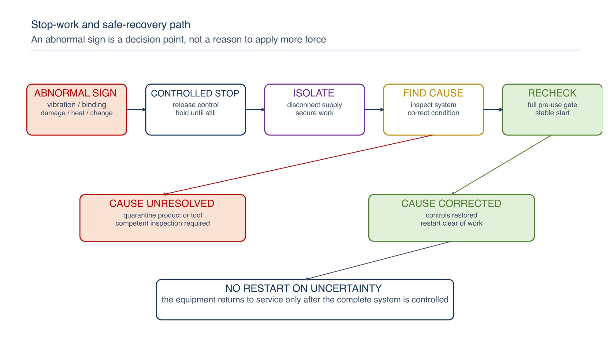
Stop work when control is lost or uncertain
Stop, isolate and assess when any of the following occurs:
- unusual vibration, sound, smell, smoke or visible runout;
- cracked, chipped, torn, distorted, loaded or contaminated abrasive product;
- loose product, guard, handle, flange, backing pad or workpiece;
- binding, kickback, repeated stalling or speed instability;
- damaged cable, battery, hose, coupling, plug, switch or control;
- guard movement or contact between the product and guard;
- excessive heat, unexpected discolouration or sparks outside the controlled path;
- extraction failure or visible dust escaping the control zone;
- entry of another person, vehicle or obstruction into the work area;
- changing weather, water, ventilation or hazardous-area condition;
- loss of stable footing, visibility, grip or access; or
- uncertainty about product marking, speed, mounting or intended use.
Do not resume merely because the symptom disappears after stopping. Identify and correct the cause, replace damaged components, and repeat the full pre-use and safe-start sequence.
Troubleshoot unsafe symptoms
| Symptom | Likely contributors | Safe response |
|---|---|---|
| Strong vibration immediately after start | Damaged product, dirty or mismatched flange, incorrect seating, spindle condition or incompatible mounting | Stop and isolate; remove and inspect the complete mounting system; do not test by applying work |
| Wheel or disc repeatedly loosens | Incorrect mounting parts, direction, tightening method, worn spindle or incompatible product | Remove from service and verify the prescribed mounting system and tool condition |
| Cutting wheel binds | Workpiece closes the kerf, poor support, misalignment, twisting or excessive force | Stop, isolate and stabilise; correct support and alignment before inspecting and restarting clear of the cut |
| Tool kicks or climbs | Edge impact, wrong direction of approach, excessive depth, unsuitable product or unstable grip | Stop and reassess product, work support, direction, access and body position |
| Excessive heat or burning | Excessive pressure, poor movement, loaded or unsuitable abrasive, restricted airflow or incorrect process | Stop, allow safe cooling and correct selection, technique and ventilation |
| Guard cannot be positioned effectively | Incorrect tool, guard or product geometry; restricted access | Change the setup; do not remove or modify the guard |
| Dust escapes extraction | Poor capture position, blocked duct, insufficient airflow, unsuitable system or changed process | Stop and restore effective source control before resuming |
| Speed sounds unstable | Supply, regulator, battery, motor, control or tool-maintenance issue | Isolate and remove tool from service for competent inspection |
| Product marking is unreadable | Wear, contamination, poor storage or loss of label information | Do not use until identity and all critical compatibility information are reliably established |
| Product performance falls suddenly | Damage, loading, glazing, contamination, material change or tool fault | Stop and inspect; do not compensate with greater force |
Troubleshooting must preserve the safety boundary. Never diagnose a suspected mounting, guard, spindle or product fault while the tool is energised or coasting.
Abrasive safety release checklist
Before starting a grinding, cutting, sanding or polishing task, confirm:
- [ ] the task, material, coating and environment have been assessed;
- [ ] elimination, substitution and engineering controls have been considered;
- [ ] the operator is trained and authorised for the tool and task;
- [ ] product identity, intended use and marking are legible;
- [ ] operation, material, dimensions, attachment, direction and speed are compatible;
- [ ] the correct guard and mounting parts are installed and secure;
- [ ] the abrasive product, tool, spindle, handle, controls and supply are undamaged;
- [ ] mounting was completed with energy isolated and without force or improvisation;
- [ ] the workpiece and offcut are supported against movement and binding;
- [ ] the spark, fragment, dust and reaction-force zones are controlled;
- [ ] combustible material and vulnerable equipment are removed or protected;
- [ ] extraction and ventilation are operating as required;
- [ ] PPE is selected, fitted and in serviceable condition;
- [ ] cable or hose routing, footing, access and lighting are safe;
- [ ] nearby personnel are outside the controlled area;
- [ ] the no-load start is stable and free from unusual vibration or sound;
- [ ] the operator knows the stop-work conditions; and
- [ ] post-use isolation, cooling and storage arrangements are ready.
Personal Protective Equipment
The Personal Protective Equipment chapter (047) appears on the following page of the printed handbook (page 407), outside this chapter extract.