
Grinding operators, supervisors, production engineers, maintenance personnel, QA/QC teams and technical buyers
Stop conditions; evidence preservation; vibration and chatter; heat and burn; slow cutting; rapid wear; loading and glazing; poor finish; deep scratches; geometry loss; edge damage; dust and swarf; hand-held and stationary grinding; controlled correction and verification.
Never troubleshoot a rotating or energised machine by touching the abrasive, mount or workpiece. Isolate before inspection or adjustment. Do not exceed marked limits, defeat guards, use a damaged product, force a poor-cutting wheel, dress an unsuitable product or continue after abnormal vibration. Confirm the exact product, machine, accessory, workholding, extraction and PPE requirements.
A grinding symptom is evidence, not a diagnosis. Check the product, machine, mounting, support, workpiece, method and environment before assigning the cause.
Grinding performance depends on a connected system. A sound abrasive can behave poorly on a worn machine, incorrect support pad, unstable fixture or contaminated surface. Conversely, changing the machine or technique cannot make a damaged or incompatible wheel safe. Effective troubleshooting separates immediate stop conditions from process symptoms, preserves evidence and changes one controlled factor at a time.
When an exact product value is required, Refer to the product label, Technical Data Sheet, or MKTECH representative.
Chapter objectives
After this chapter, the reader should be able to:
- recognise conditions that require immediate stop and isolation;
- record a grinding symptom without destroying evidence;
- inspect the complete product–machine–workpiece system;
- distinguish vibration, heat, cutting, wear, loading and finish problems;
- select safe first checks before changing a specification;
- separate hand-held and stationary-machine mechanisms;
- avoid corrections that create a new hazard or defect;
- verify corrective action against accepted output; and
- escalate repeat or high-consequence problems through controlled review.
Stop first when the condition is unsafe
Stop, isolate and inspect when there is:
- a crack, tear, separation, deformation or missing abrasive section;
- sudden or increasing vibration, chatter or abnormal noise;
- loose mounting, movement at the flange, pad, adaptor or mandrel;
- contact between the abrasive and guard or machine structure;
- damaged guard, handle, work rest, control or power connection;
- unstable workholding, pinching, kickback or loss of work control;
- smoke, fire, unexpected sparking location or suspected combustible dust event;
- suspected overspeed, wrong product identity or missing marking; or
- any condition outside the approved method.
Manufacturer guidance specifically advises stopping immediately when a tool begins to chatter or vibrate and finding the cause before continuing. [S390] Do not perform a test pass with an already suspect product.
Preserve the evidence
Before cleaning, dressing, discarding or adjusting, record:
- product identity, lot/batch and visible condition;
- machine, accessory and mounting arrangement;
- workpiece material, geometry and incoming condition;
- operation, processing stage and acceptance requirement;
- location and pattern of the symptom;
- operator observations of sound, vibration, force, sparks, swarf and heat;
- elapsed use or accepted output since change-out;
- extraction, coolant or lubricant status where applicable; and
- recent changes to product, material, machine, fixture or method.
Photograph the product and workpiece safely after isolation. Segregate damaged or unidentified abrasives so they cannot return to use.
Use a complete-system diagnostic sequence
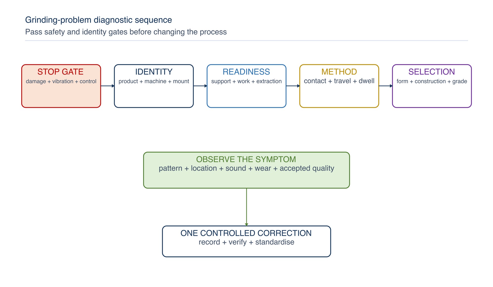
Check in this order:
- safe condition and product identity;
- machine and mounting condition;
- support accessory, work rest and workholding;
- workpiece material, coating and incoming variability;
- contact, travel, dwell, overlap and operator control;
- extraction, chip clearance or coolant condition; and
- abrasive form, construction and grade family.
This order finds common physical causes before introducing a new product variable.
Build a symptom map
| Symptom | Immediate concern | First diagnostic focus |
|---|---|---|
| Sudden vibration or chatter | Product damage, loose mount, contact or unstable work | Stop; inspect product, mount, machine and fixture |
| Burn, heat tint or distortion | Thermal damage and altered geometry | Hold work; inspect cutting action, dwell and cooling |
| Slow cutting or rising force | Dulling, glazing, loading, machine output or wrong selection | Inspect abrasive face and complete contact system |
| Rapid abrasive loss | Excess force, impact, unsuitable construction or support | Inspect wear pattern and workpiece presentation |
| Loading | Removed material obstructs cutting surface | Check material, contamination, openness and chip clearance |
| Glazing | Dull surface is not renewing effectively | Check selection, engagement, dressing permission and method |
| Deep or random scratches | Coarse particle, contamination, torn product or sequence error | Stop transfer; clean and inspect |
| Wavy or uneven finish | Vibration, runout, support wear, overlap or workholding | Compare pattern with machine and contact motion |
| Edge gouging or undercut | Localised contact, hard support, high presentation angle or dwell | Inspect access, pad and edge technique |
| Dimensional or form error | Excess removal, deflection, thermal growth or wheel truth | Hold work and verify geometry |
One symptom can have several causes, and one cause can create several symptoms.
Vibration and chatter
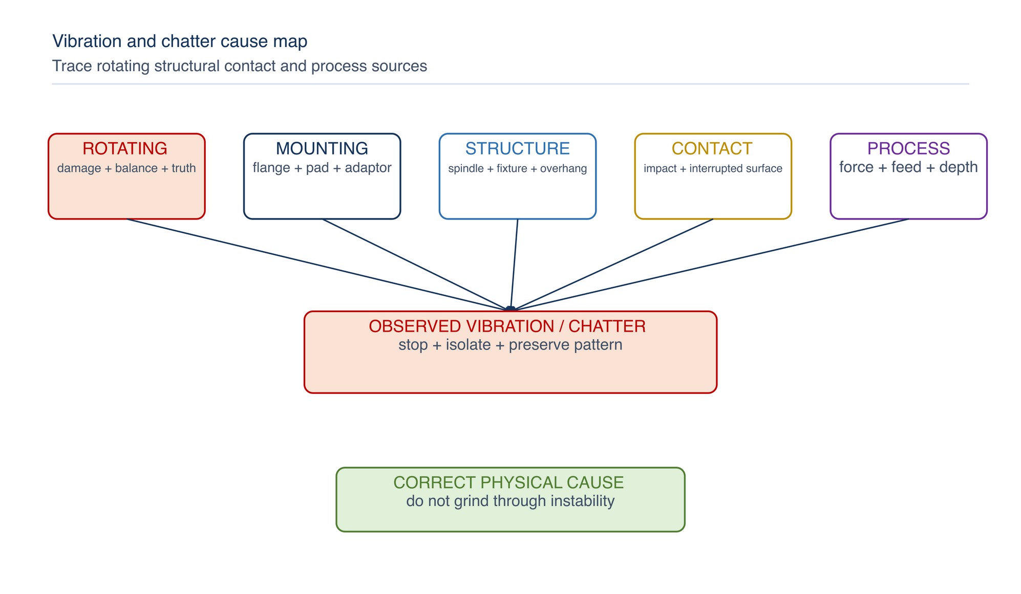
Check:
- damaged, distorted or out-of-balance abrasive;
- debris, burrs or incorrect contact at mounting faces;
- loose flange, adaptor, mandrel, collet or backing pad;
- spindle, bearing, drive or air-supply condition;
- guard or accessory contact;
- wheel truth and permitted dressing condition on stationary equipment;
- worn support pad, contact wheel or work rest;
- excessive product or workpiece overhang;
- flexible, loose or resonant workholding;
- intermittent edge contact or impact; and
- force, feed or depth beyond stable engagement.
Chatter can result from loss of truth, mounting slip, wheel condition or insufficient work support. [S389] HSE guidance also connects dull, hard-cutting wheels and excessive force with greater vibration and wheel-distortion risk. [S378]
Do not balance, true or dress a product unless the exact product and machine system permits it and the task is performed by an authorised person.
Burning, heat tint and distortion
Heat can be generated by rubbing, dull grains, loading, excessive engagement, long dwell, poor coolant delivery, inadequate chip clearance or a sequence that concentrates heat. Check:
- whether the abrasive is cutting or rubbing;
- loading, glazing or contaminated surface;
- rising operator force;
- dwell, overlap and repeated passes in one zone;
- contact area and support hardness;
- machine output and speed control;
- workpiece thickness, restraint and heat sensitivity;
- coolant delivery, condition and filtration where applicable; and
- abrasive construction and grain-renewal behaviour.
Surface-grinding guidance links friction and heat with chatter, burn and poor finish, and includes grain condition, structure, dressing and coolant among the variables. [S391]
Visible colour removal does not prove that thermal or metallurgical damage is absent. Apply the controlled acceptance and inspection method appropriate to the component.
Slow cutting and rising force
When cutting action declines, do not simply press harder. Inspect for:
- abrasive surface loaded with swarf, coating, adhesive or residue;
- glazed or polished cutting surface;
- worn or unsuitable support accessory;
- low machine output, supply restriction or speed-control fault;
- excessive contact area;
- incorrect abrasive form, grain family, grit or construction;
- workpiece hardness or coating different from the expected condition;
- inadequate extraction or chip clearance; and
- product used beyond its efficient or safe condition.
Measure accepted output and task time together. A product that remains physically present but no longer cuts efficiently can increase labour, force, heat and exposure.
Rapid abrasive wear or shedding
Inspect the wear pattern. Uniform controlled wear differs from local edge loss, tearing, chunking or one-sided wear. Likely causes include:
- excessive force or feed;
- impact on edges, projections or interrupted surfaces;
- unsuitable product construction for contact severity;
- excessive flex or insufficient support;
- incorrect pad, flange, contact wheel or mandrel;
- misalignment or poor tracking;
- unstable workpiece;
- heat or chemical contamination; and
- use on a prohibited face or edge.
Do not select a harder or more durable product solely to reduce visible wear. Preserve cutting efficiency, controllability, accepted quality and safe use.
Loading
Loading occurs when removed material or residue occupies the abrasive surface and obstructs cutting. It may appear as metallic transfer, packed dust, coating or smeared material. Check:
- soft or ductile material behaviour;
- paint, scale, adhesive, grease or sealant;
- abrasive openness and chip space;
- grit and construction suitability;
- contact pressure and dwell;
- extraction, air flow or approved coolant;
- support condition and contact area; and
- cross-contamination from previous work.
Do not strike, scrape, burn or solvent-clean a loaded abrasive unless an approved product-specific method permits it.
Glazing
Glazing is a dull, smooth condition in which the abrasive surface no longer renews effectively. The operator may hear a changed sound and apply increasing force while removal falls. Possible contributors include:
- abrasive grade or bond too durable for the engagement;
- insufficient effective engagement;
- inappropriate machine or work speed relationship;
- large contact area with low grain penetration;
- ineffective or overdue permitted dressing;
- contaminated coolant or workpiece; and
- machine output below the intended operating condition.
Loading and glazing can occur together, but they are not identical. Inspect the surface and process evidence before changing the abrasive.
Poor or inconsistent finish
Check whether the defect is random, directional, periodic or concentrated at an edge. Then inspect:
- grit and stage progression;
- complete removal of previous-stage scratches;
- torn, contaminated or locally worn abrasive;
- support-pad or contact-wheel condition;
- runout, truth, balance and vibration;
- workholding and component deflection;
- travel speed, overlap, direction and dwell;
- cleaning between stages; and
- inspection lighting, comparator and measurement method.
Grit designation alone does not guarantee a finish. P, F and superabrasive designations belong to different standards contexts and should not be converted casually. [S346; S347; S348; S349]
Deep scratches and stray marks
Deep scratches commonly originate from:
- a retained coarse particle from an earlier stage;
- contaminated bench, glove, cloth, compound or work support;
- torn backing or exposed product edge;
- loose swarf trapped under the abrasive;
- incorrect first contact or tool placement;
- mixing products between carbon steel, stainless steel or non-ferrous work; and
- handling after finishing.
Stop before carrying the defect through finer stages. Clean the workpiece and equipment, identify the scratch depth and return to the earliest necessary correction stage without removing more material than permitted.
Wavy, lobed or periodic marks
A repeating pattern often points to a repeating mechanical or motion source. Compare mark spacing and direction with:
- wheel, disc, pad or spindle rotation;
- belt splice or contact-wheel rotation;
- workpiece rotation or feed;
- machine vibration or nearby equipment;
- fixture resonance;
- cyclic operator motion; and
- intermittent contact from runout or loss of truth.
Stationary grinding guidance emphasises rigid work support because vibration produces chatter or wave marks. [S389] Correct the mechanical source before changing grit.
Edge gouging, undercut and geometry loss
Edges concentrate contact and can remove material quickly. Check:
- approach and presentation angle;
- pad hardness and product flexibility;
- contact on the product edge rather than supported face;
- dwell at starts, stops or direction changes;
- fixture obstruction and poor visibility;
- excessive force;
- abrasive too aggressive for the final geometry; and
- missing protection for adjacent datum or finished surfaces.
Use suitable fixtures, templates or protected zones where approved. Confirm dimensions after correction; visual blending alone does not prove geometry is acceptable.
Cracking, chipping or product separation
Treat any crack, chunk loss, delamination, hub damage or separation as a stop condition. Possible origins include impact, poor storage, incorrect mounting, flange mismatch, excessive side pressure, workpiece movement, pinching, wrong machine use or overspeed.
Do not re-mount a damaged product to reproduce the symptom. Preserve it for examination and inspect related stock, packaging, machine mounting parts and workpiece support. Current standards distinguish intended product and machine scopes; for example, angle-grinder grinding wheels, pneumatic grinders, die grinders and stationary grinding machines are not interchangeable categories. [S278; S280; S282; S283; S284]
Dust, swarf and extraction problems
Poor capture can obscure the contact zone, promote loading, contaminate surfaces and increase worker exposure. Check:
- hood or nozzle position;
- blocked hose, duct or filter;
- damaged connection or leakage;
- collector and fan status;
- product/work orientation relative to capture;
- material-specific combustible-dust and contamination controls; and
- whether the extraction system is suitable for the actual dust and spark stream.
Never direct hot sparks or incompatible dust into an unsuitable collector. Apply the workplace chemical and combustible-dust risk controls.
Hand-held grinder problems
For hand-held operations, give particular attention to:
- two-hand control and handle position;
- operator stance and line of fire;
- cable, hose or battery condition;
- guard and accessory compatibility;
- disc/pad support and secure mounting;
- workpiece security and access;
- tool power under load;
- edge striking, rocking and dwell; and
- increasing fatigue or force.
The operator is part of the control loop, but repeated difficulty across operators often indicates selection, access, support or equipment problems rather than individual technique alone.
Stationary grinding problems
For bench, pedestal, surface and other stationary grinding systems, check the applicable machine-specific controls, including:
- wheel mounting, flanges and blotters where required;
- guard and work-rest condition;
- spindle, bearing and drive condition;
- wheel truth, balance and permitted dressing;
- table, chuck, centres or fixture rigidity;
- feed, infeed and work-speed controls;
- coolant delivery, concentration, filtration and temperature where applicable; and
- machine foundation and external vibration.
ISO 16089:2025 provides a current safety framework for specified stationary grinding-machine groups. [S284] It does not replace the machine manual or confirm that a particular wheel, guard or process is suitable.
Apply one controlled correction
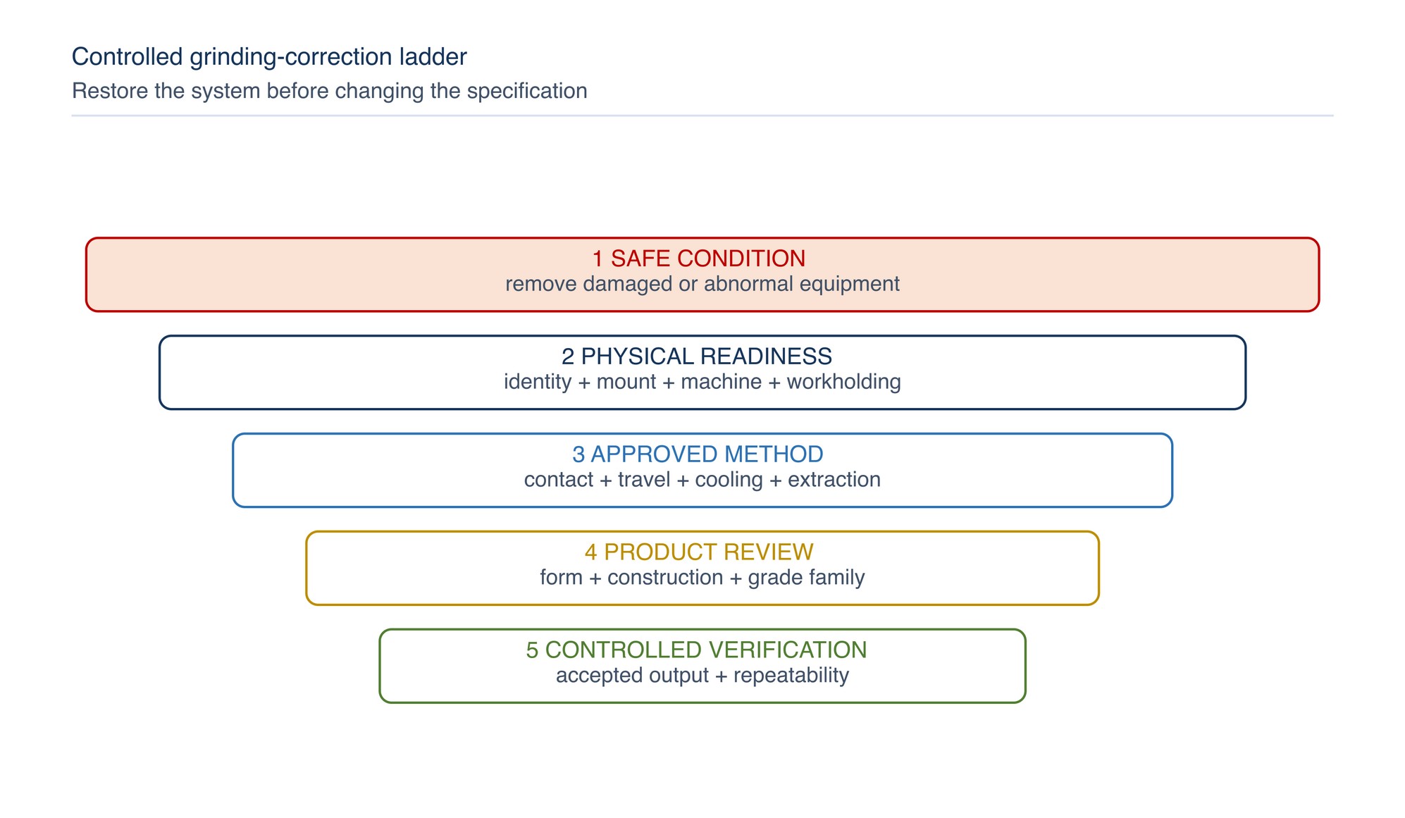
Use the least disruptive verified correction:
- remove unsafe or damaged equipment/product from service;
- restore identification, correct mounting and support;
- correct machine, extraction, coolant or workholding condition;
- restore the approved contact and travel method;
- condition or dress only where specifically permitted;
- review product form, construction and grade family; and
- conduct a controlled comparison before specification change.
Record what changed. Multiple simultaneous changes may hide the cause and make the result impossible to reproduce.
Verify and sustain the correction
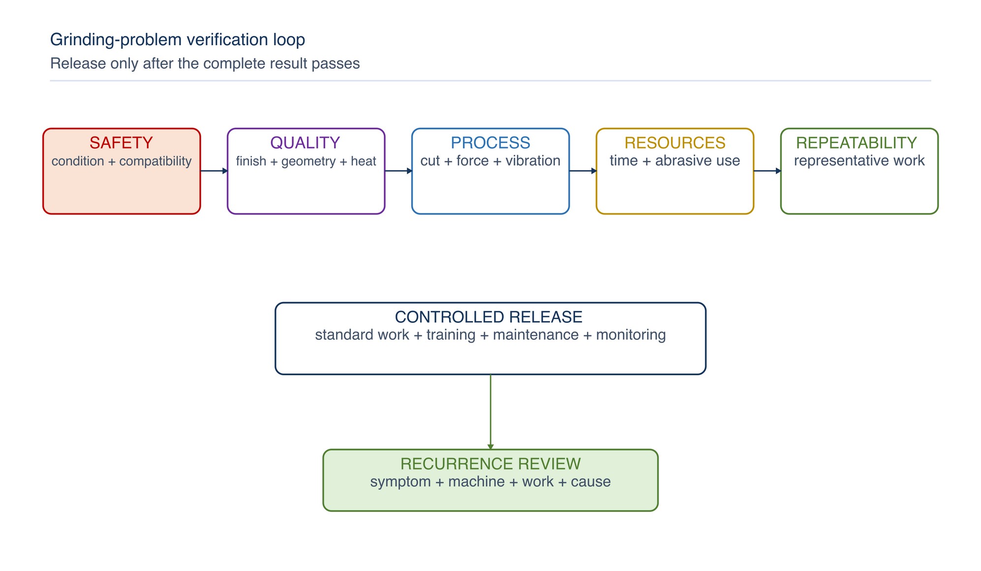
Confirm:
- safe condition and compatibility;
- accepted finish, dimensions and geometry;
- absence of unacceptable thermal or surface damage;
- stable sound, vibration and operator control;
- productive cutting without abnormal force;
- task time and abrasive use on an accepted-output basis;
- repeatability across representative work; and
- updated standard work, training or maintenance action.
Monitor recurrence by symptom, product, machine, work family and originating cause. Use Chapter 063 for controlled product or method trials and Chapter 066 for ongoing indicators.
Rapid troubleshooting table
| Problem | Check first | Controlled direction |
|---|---|---|
| Sudden vibration | Damage, mount, spindle, guard contact, workholding | Stop and correct physical cause |
| Burn or heat tint | Cutting action, loading/glazing, dwell, cooling | Reduce rubbing and restore controlled removal |
| Slow cut | Abrasive face, machine output, contact area | Diagnose before applying more force |
| Rapid wear | Force, impact, support, construction | Stabilise contact and review suitability |
| Loading | Material/residue, openness, chip clearance | Prevent packing and contamination |
| Glazing | Grain renewal, engagement, permitted dressing | Restore cutting condition under exact instructions |
| Random scratches | Contamination, torn product, trapped particle | Clean, isolate and correct from required stage |
| Wavy finish | Runout, truth, vibration, fixture | Correct repeating mechanical source |
| Edge gouge | Presentation, support hardness, dwell | Improve access and supported contact |
| Geometry loss | Excess removal, deflection, heat, measurement | Hold work and verify dimensional status |
Safety reminder
Never troubleshoot a rotating or energised machine by touching the abrasive, mount or workpiece. Isolate before inspection or adjustment. Do not exceed marked limits, defeat guards, use a damaged product, force a poor-cutting wheel, dress an unsuitable product or continue after abnormal vibration. Confirm the exact product, machine, accessory, workholding, extraction and PPE requirements.
Key takeaways
- Treat the symptom as evidence, not proof of one cause.
- Stop immediately for damage, looseness, abnormal vibration or loss of control.
- Preserve the product, workpiece and process evidence.
- Check machine, mounting, support and workholding before changing selection.
- Distinguish loading from glazing and heat from visible colour alone.
- Change one controlled factor at a time.
- Verify the complete accepted result before release.
Cutting Problems
The next chapter, Cutting Problems, begins on the following page of the printed handbook (page 623), outside this chapter extract.